PBR Journey Part 3 : Clear Coat Model with VTK
Introduction
In our last step on the Physically Based Rendering Journey with VTK, we introduced an anisotropy model to simulate materials that exhibit different reflecting properties depending on the direction of the tangent.
Today, the journey continues with the clear coat model that enables the simulation of a second, dielectric and isotropic layer on top of the object. This layer enables the reproduction of a coating such as paint on materials : the light is reflected on this layer before being transmitted to the base layer.
Concept of Index Of Refraction (IOR)
As this model simulates an interface between two mediums, we need to compute the ratio between the amount of light reflected and transmitted at this interface.
For this, we introduced the concept of Index Of Refraction in VTK. The index of refraction of a medium is a dimensionless number that describes how fast light travels through the material compared to the speed of the light in void.
With VTK, we do not as yet have a way to specify environment refractive index so we assume that the object is only surrounded by pure air, with an IOR of 1.0. Future implementations may consider an other medium to be used as the environment.
These refractive indexes are used to calculate the fresnel reflectance F0, which is the amount of energy reflected at normal incidence (ie. with an angle of 0° with the normal) at an interface between two materials A and B.
Physically, metallic materials are described by measurable complex refractive indexes, leading to a chromatic reflectance. This is what gives the metal its color. As complex IOR are not yet implemented in VTK, we assume that the reflectance F0 is its albedo (ie. the base color of the material, which can be set with `vtkProperty::SetDiffuseColor(r,g,b)`).
At the opposite, dielectrics have real refractive indexes, so F0 is achromatic and is calculated with the formula below.
$latex f_0= \frac{(IOR_a – IOR_b)^2}{(IOR_a + IOR_b)^2}&s=4$
$latex IOR_a$ is the refractive index of the medium a (typically, the base layer), and $latex IOR_b$ is the refractive index of the medium b (typically the coat layer or the environment).
Check out this great refractive index database to select the refractive index that suits your needs. Real materials have an IOR between 1.33 (water) and 2.4 (diamond).
Parameters
This model adds several options to vtkProperty :
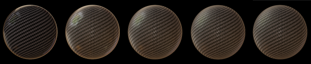
- Coat Strength: Controls the strength of the coat layer, between 0.0 and 1.0. Default is 0.0 (no clear coat). This is set using
vtkProperty::SetCoatStrength(). This parameter can be considered as the thickness of the coating.
- Coat roughness: Controls the roughness of the coat layer. Default is 0.0. This is set using
vtkProperty::SetCoatRoughness().
- Coat color: The color of the coat layer. Specular reflections on the coat layer are always white, but this parameter modifies the radiance that passes through it. Default is white (no modification of the radiance after transmission to the base layer). This is set using
vtkProperty::SetCoatColor().
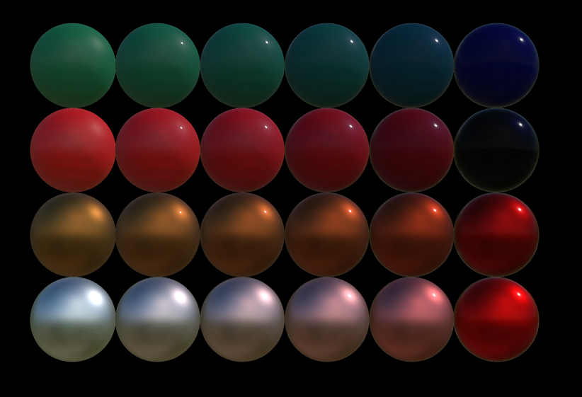
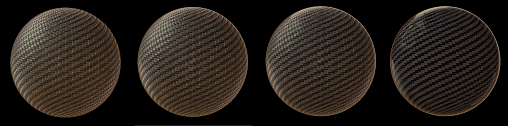
2 upper lines : Dielectric spheres with a blue coat color
2 lower lines : Metallic spheres with a red coat color
You can notice that the coat color does not influence the specular reflections on the coat layer (always white), but modifies the light color after transmission to the base layer.
- Base layer IOR : The refractive index of the base layer. Default is 1.5. This is set using
vtkProperty::SetBaseIOR().
- Coat layer IOR : The refractive index of the coat layer. Default is 2.0. This is set using
vtkProperty::SetCoatIOR().
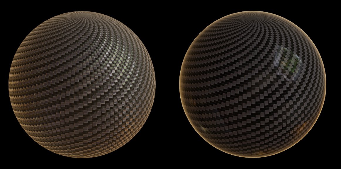
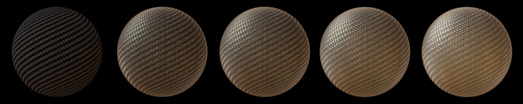
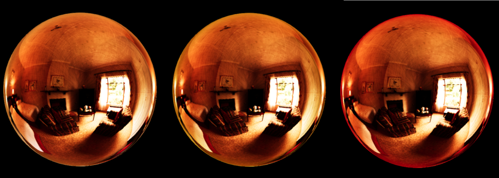
If a coat layer is present like in Figure 6, we must recompute the reflectance of the interface base-environment taking the coat layer IOR as the refractive index of the environment. Considering the above formula, it implies that :
- If the base IOR stays constant but the coat IOR goes up, the reflectance of the base layer – coat layer interface and of the coat layer-environment goes up. The figure 6 demonstrates this behavior.
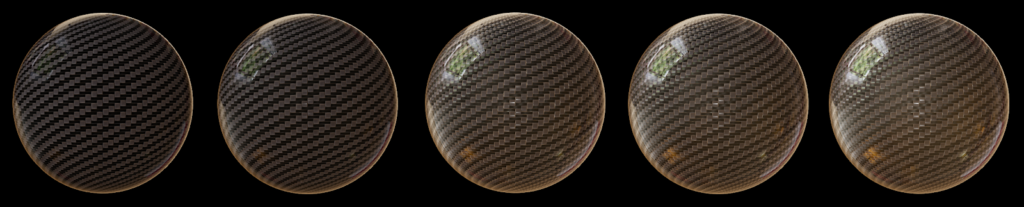
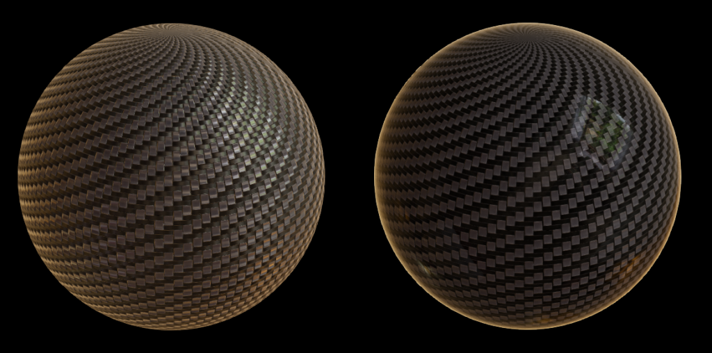
- If the coat IOR is equal to the base IOR then the reflectance of the interface base layer – coat layer will be 0. That means that if you want to add more coat specular reflection without adding base specular reflection, you must set the base IOR equal to the coat IOR, like depicted in the Figure 7 below.
- Edge Tint : The fresnel reflectance F0 is the amount of light reflected at normal incidence (ie. with an angle of 0° with the normal). Similarly, a fresnel reflectance F90 exists which is the amount of light reflected at grazing angles (ie. with an angle of 90° with the normal). As F90 is always 1.0 (and achromatic) for dielectrics, it is chromatic for metals and can now be parameterized by setting
vtkProperty::SetEdgeTint. This property sets the color of the reflection on the edges of a metallic material.
What’s next
Clear coat model will be available in ParaView 5.10 and in nightly builds.
A lot of things can be done to enhance the rendering in VTK. What we have in mind:
- Complex IOR for metals
- Ability to change the refractive index of the environment
- Subsurface scattering
- Emissive bloom
And a lot more ! Stay tuned !
Acknowledgements
This work is funded by an internal innovative effort of Kitware Europe.