PBR Journey Part 1: High Dynamic Range Image Based Lighting with VTK
Introduction
Last year we introduced the beginning of Physically Based Rendering in VTK. Now the journey to modern rendering in VTK continues with new features that allow to render more realistic scenes.
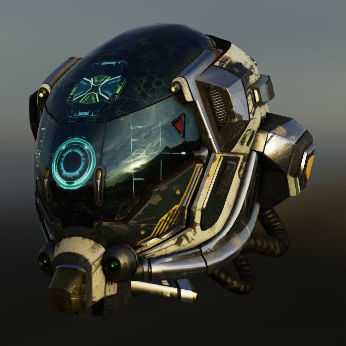
With the newly added HDR reader in VTK 9.0, it is now possible to load a High Dynamic Range (.hdr file) image into a cubemap texture. This texture can then be used for Image Based Lighting (IBL). Unlike traditional images that encode pixel value between 0 and 1, HDR images encode pixels without a max bound. Information stored in a HDR image corresponds to a physical value of luminance, as opposed to a traditional low dynamic range image where information represents colors as they should appear on the screen. We can now consider a pixel value as a light source, and this allows rendering more details in the environment and more realism in reflections as depicted in the figure 1. This post will explain what you should know about this new feature.
Sampling artifacts
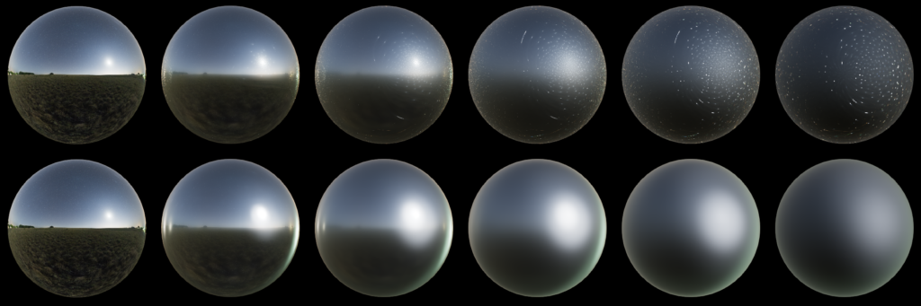
To improve performances in real time rendering for IBL, we precompute the information needed for the specular (see vtkPBRPrefilterTexture) and diffuse (see vtkPBRIrradianceTexture) reflection by sampling the environment into different textures. However, when the texture is created from a HDR image, due to the presence of high frequency, it can produce undesired sampling artifacts during the computation for higher roughness levels in both diffuse and specular contribution.
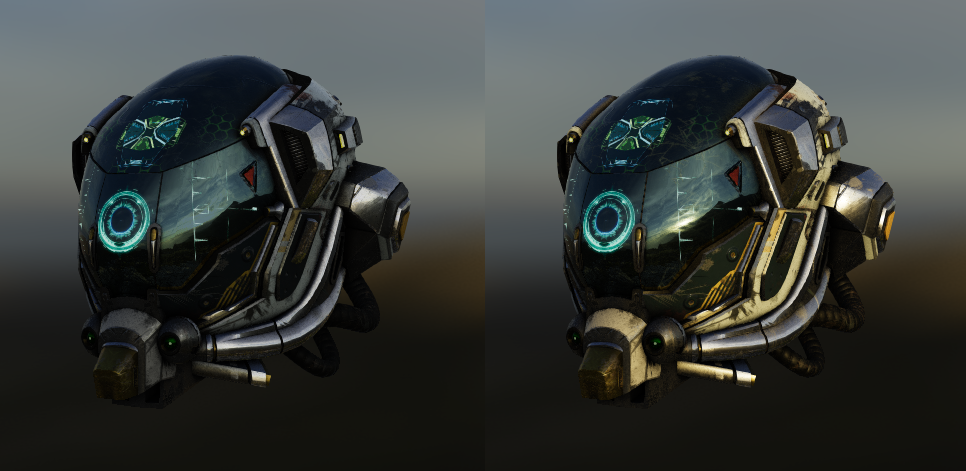
Regarding the specular contribution, in order to remove the artifacts visible in Figure 2, the precomputation exploits hardware capabilities to use a mipmapped texture to sample at a higher mip level (with interpolated lower resolution) when the roughness is increased.
To enable mipmapping, set vtkTexture::MipmapOn() and vtkTexture::InterpolateOn(), as seen in the example below :
vtkNew<vtkHDRReader> reader;
reader->SetFileName("image.hdr");
reader->Update();
vtkNew<vtkTexture> texture;
// Enable mipmapping to handle HDR image
texture->MipmapOn();
texture->InterpolateOn();
texture->SetInputConnection(reader->GetOutputPort());
renderer->UseImageBasedLightingOn();
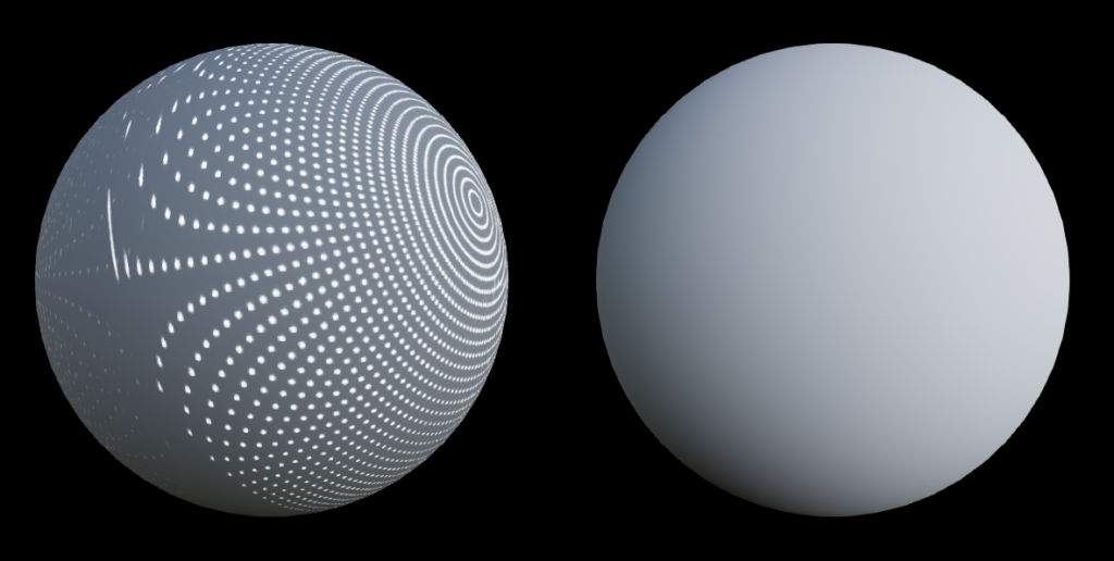
renderer->SetEnvironmentTexture(texture);Regarding the diffuse contribution, a new default algorithm based on spherical harmonics has been introduced which is more efficient and has lower memory print. Moreover, all artifacts are removed as depicted in Figure 3. This is an approximation but the quality should be good enough for all cases. To fall back to the previous algorithm, you can set vtkOpenGLRenderer::UseSphericalHarmonicsOff().
Tone mapping
In order to properly display High Dynamic Range images on a monitor, the tone mapping has been updated. The tone mapping maps a HDR pixel value to a value between 0 and 1 that can be shown on the screen. Before VTK 9.1, there were 3 tone mapping methods : Clamp, Reinhard and Exponential. Although these methods work well, especially Reinhard with the soft highlights, the blacks are not well saturated. The new Generic Filmic tone mapping operator allows to configure the shadows as well as the highlights by setting various parameters to reshape the tone mapping curve drawn in Figure 4.
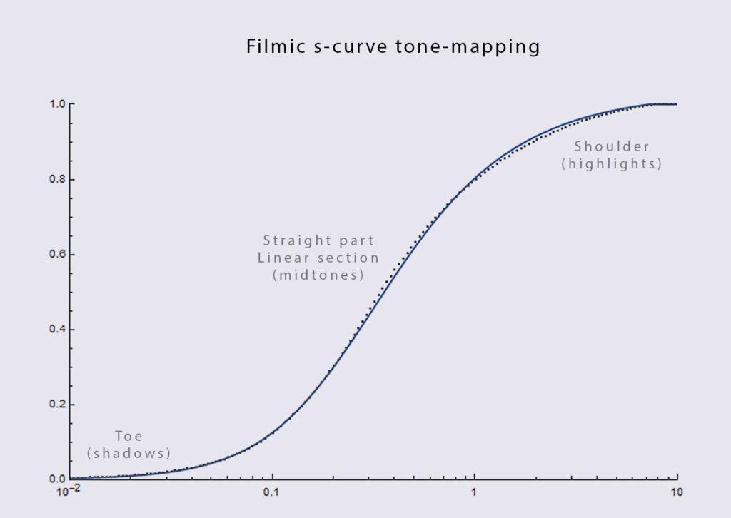
- Contrast: Typically in [1-2]. Adjusts the toe (left part) of the curve. Controls the shadows and intensity of black.
- Shoulder: Typically in [0.9-1]. Adjusts the right part (the highlights).
- MidIn, MidOut: MidIn and MidOut adjust the middle gray level in percent of the curve for input and output (ie. the halfway point between white and black). Default for both is 18 %.
- HdrMax: Specify the maximum HDR input that is not clipped.
- UseAces: Allows the use of the Academy Color Encoding System (ACES) which defines an ultimate color-space with an ultra wide gamut that includes most colors spaces. Default is true.
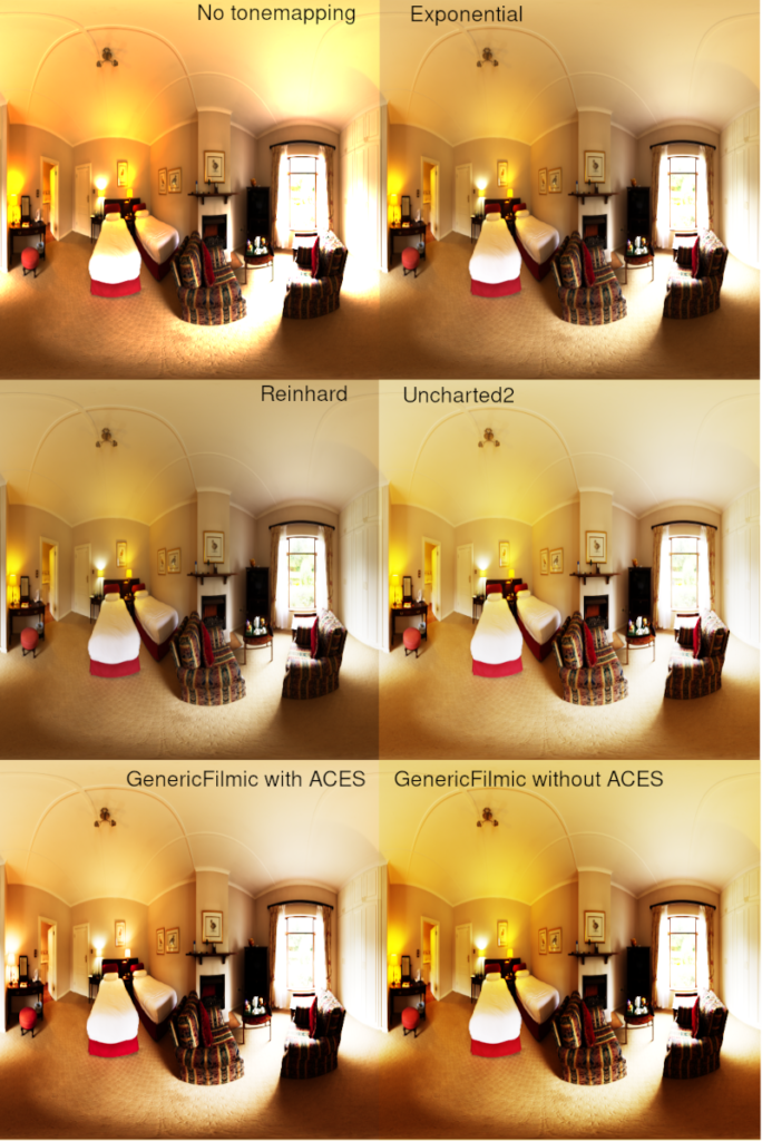
Figure 5 compares the different tonemapping operators provided in VTK. You can notice that the new default Generic Filmic operator saturates the blacks while preserving nice colors highlights.
What’s next
Image based lighting with a HDR image and the tone mapping will be available in ParaView 5.9.
In the upcoming part II of our PBR journey we will introduce an anisotropic microfacet model to simulate materials that exhibit variations in physical properties along different axes. Stay tuned!
Acknowledgements
This work is funded by an internal innovative effort of Kitware Europe.