Representing Geometric Models with SMTK
Over the last several decades, the introduction of high-performance computing (HPC) simulation practices has enabled scientists to model complex physical systems. It has also resulted in improved products and manufacturing procedures. Today, there are many sophisticated simulation tools and toolkits that are distributed through both commercial and open-source licenses. Solid modeling kernels such as 3D ACIS Modeler (ACIS), Parasolid, and Open CASCADE provide access to computer-aided design (CAD) models and advanced operations. Meshers and meshing toolkits including CUBIT Geometry and Mesh Generation Toolkit [1], Capstone, MeshKit, and MeshSim produce meshes with characteristics that are required by analyses. OpenFOAM, Hydra, and Albany offer open-source alternatives to commercial technologies and take full advantage of HPC systems running on hundreds of thousands of cores. Solutions like ParaView even provide in situ support for simulation runs, as demonstrated by ParaView Catalyst [2].
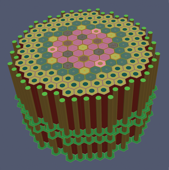
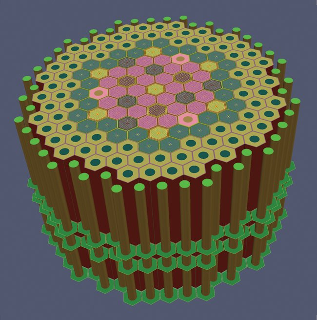
Figure 1: A complex geometric model of an Advanced Burner Test Reactor (ABTR) being prepared for a simulation in Computational Model Builder.
The issue is that the above-mentioned technologies are only pieces of the simulation puzzle; individually, none address the full simulation life cycle. The task of integrating the puzzle pieces into specific workflows is generally left to manufacturers, engineers, and researchers, who must also navigate various job submission systems associated with HPC and cloud-based technologies.
To tackle the full simulation life cycle, Kitware is developing the Computational Model Builder (CMB) [3] framework and application suite. The development effort [4] centers on managing the core resources required to define a simulation. These resources are geometric models, simulation information, and meshes.
As part of CMB, we created a light-weight library known as Simulation Modeling Toolkit (SMTK). Unlike other open-source libraries, SMTK supports all three core resources, in addition to the inter-relationships that exist between them. SMTK presents an interface for representing geometric models and meshes, the operations that can be performed on the models and meshes, and complex structures. Complex structures are often necessary to model information required by a simulation (e.g., boundary conditions and material definitions). SMTK associates this information with various components of the geometric domain in order to define a complete simulation model.
SMTK is written in C++ and includes Python wrappers. The toolkit is distributed under a Berkeley Software Distribution (BSD) license and is available via CMB’s website [5]. The relationship between SMTK and CMB is analogous to the relationship between the Visualization Toolkit (VTK) [6] and ParaView [7]. Both VTK and SMTK offer necessary functionality via libraries, while CMB and ParaView provide the application frameworks.
What is a Geometric Model
SMTK aims to integrate models from a variety of sources by exposing a common interface for accessing model entities across different modeling kernels. Supported modeling kernels include the following:
- parametric kernels, where volumes, faces, and edges have well-defined parametric coordinates that can sufficiently represent curved models; and
- discrete kernels, where volumes, faces, and edges are each discretized into a piecewise collection of primitive cells, which may have internal parameterizations but do not guarantee a parameterization at the model-entity level.
Each modeling kernel, whether discrete or parametric, provides model representations with varying levels of fidelity, from simple unstructured point clouds to triangles complete with non-manifold boundary representations. The fidelity involved depends on which modeling kernel an SMTK session uses, as well as on the choices made by the modeling kernel when constructing a model.
Models are composed of geometric entities and relationships between entities, depending on levels of fidelity. Supported geometric entities are as follows:
- vertices, representing topological domains of dimension 0;
- edges, representing topological domains of dimension 1;
- faces, representing topological domains of dimension 2;
- volumes, representing topological domains of dimension 3;
- groups (or collections), consisting of model entities; and
- models (or parts), representing assemblies.
Relationships, such as those regarding “use” and “sidedness,” are utilized to properly model contact between geometric entities. When one side of a model face is part of the boundary of a model volume, for example, we say that the volume “uses” the face. In cases of non-manifold topologies, each geometric entity (vertices, edges, and faces) has multiple “uses.” A face can be “used” by at most two volumes, since it has only two sides. By tracking face “uses” explicitly, SMTK allows multi-physics codes to assign boundary conditions for different physical phenomena to different sides of faces.
Examples
For an illustration of the range of models supported by STMK, consider the following concrete examples.
Open CASCADE and ACIS CAD Models
Open CASCADE and ACIS CAD models are accessible—based on Computer Graphics Metafile’s (CGM’s) parametric interface—to read Standard for the Exchange of Product Data (STEP), Initial Graphics Exchange Specification (IGES), Standard ACIS Text (SAT), and other CAD files. Open CASCADE and ACIS CAD models include both geometric entities and non-manifold topological relationships between entities.
Discrete Models
Discrete models such as two-dimensional geographic shapefiles, three-dimensional (3D) STereoLithography (STL) or object (OBJ) files, and many other file formats are modeled using a VTK-based kernel packaged with SMTK. Discrete models may include full non-manifold topology.
Exodus Meshes
Models based on Exodus meshes are created via a custom model session packaged with SMTK. (Model sessions are described in the next section.) This session presents each Exodus block and side set as an SMTK group entity. SMTK assumes that the blocks and side sets in the Exodus mesh represent a meaningful partitioning (or conceptualization) of the discrete information. SMTK also assumes that the partitioning is sufficient to assign the necessary material properties, boundary conditions, and other information required by a simulation.
You may use Exodus meshes for complex models whose “formal” non-manifold representations would contain hundreds of thousands of model faces and volumes. For example, the mesh depicted in the model in Figure 1 is a 750 MB Exodus file. Rendering this file generates 21 million triangles. The model is courtesy of Argonne National Laboratory and was generated using Reactor Geometry Generator (RGG) [8], Scalable Interfaces for Geometry and Mesh Based Applications (SIGMA) tools [9] from the Department of Energy, and CUBIT Geometry and Mesh Generation Toolkit.
SMTK’s Model Manager and Model Session
SMTK stores all of the geometric entities and their relationships in a model manager. A manager can hold entities from multiple modeling kernels, providing uniform access to the entities. A manager can also serialize and deserialize entities.
Each manager’s entities are kept up-to-date by one or more model sessions. A session associates a manager’s entities to the entities’ counterparts in a single modeling kernel. Figure 2 shows a conceptual diagram of an application accessing three models within a single model manager. Each of the model entities comes from a unique session. The sessions use different modeling kernel application programming interfaces (APIs) to load and traverse models, to create entries in the model manager, and to perform operations on the models. The APIs utilized in the figure are CGM, SMTK’s built-in discrete modeler, and Capstone.
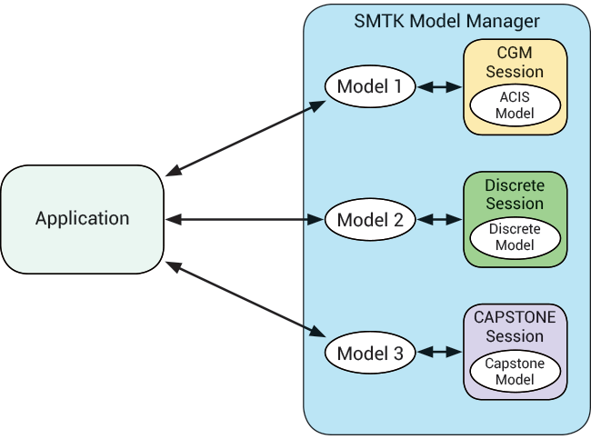
Figure 2: Accessing SMTK models within the same process space.
Since each session potentially uses a unique modeling kernel, you have access to different operations for various sessions. For example, you may have access to operations for creating vertices, edges, and faces; for sweeping parametric faces to form volumes; and for changing the assignment of discrete-modeling primitives from one edge or face to another. You may also have access to Boolean point-set operations like unions, intersections, and subtractions.
In SMTK, you can ask model sessions for a list of operators that can act on model entities in a particular session. You can also programmatically query operators for the inputs they require. In addition, you can query operators for textual descriptions of their effects.
For each operation, SMTK generates a user interface, which is discussed in more detail below.
Sessions and Processes
Some modeling kernel APIs link to conflicting versions of libraries, or they have cumbersome licensing or stability issues, making it undesirable for a single model manager to handle a given set of kernels. SMTK works around this by providing a forwarding session, which serializes and deserializes the data in a remote process’ model manager in response to operations that are forwarded to the session. You can use the same concept of forwarding to make client-server applications. Figure 3 shows how a ParaView-based application in CMB implements a forwarding session.
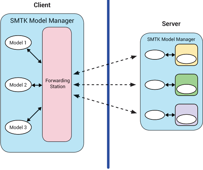
Figure 3: Supporting a client/server workflow in SMTK’s model environment.
As forwarding sessions are used across processes, SMTK is intended to grant read-only access to the contents of the model manager. To change the model, always use an SMTK operator, as opposed to changing records in the model manager. Doing the latter will not update the model in the underlying modeling kernel.
Keeping the information in the model manager to a minimum and developing clients that do not request large amounts of data to be serialized reduces the amount of work that needs to be redone after performing modeling operations. For example, the renderings in Figure 4 were completed on the server, while the model trees to the right of the renderings were drawn on the client. Since the client does not use any tessellation information itself, the model trees do not need to be serialized.
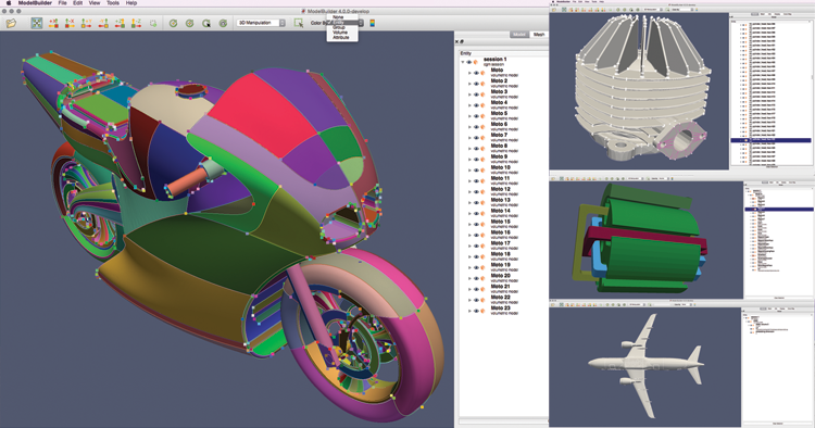
Figure 4: SMTK displaying CAD models using linked VTK and Qt-based views.
Geometric Modeling Operators
As mentioned earlier, each modeling session provides a different set of operators that you can use to alter the geometric domain intended for discretization into a mesh for a simulation. The only way to modify a model and to guarantee that changes are propagated from SMTK’s model manager to the modeling kernel is to employ operators.
Each operator accepts parameters and associations that fully specify a task for the modeling kernel. Associations bind one or more model entities to the operator as the primary geometry that the operation will affect. For instance, the Boolean union operator uses any associated geometry as the workpiece (i.e., the part that remains after subtraction) and has a parameter named “tool,” which accepts geometry to add to the workpiece.
Figure 5 shows user interfaces that are automatically generated for each operation. Buttons located next to an association or parameter entry indicate that a list of geometric entities is expected for that entry. The buttons allow you to reset the list of entities or to populate an entry with the current selection.
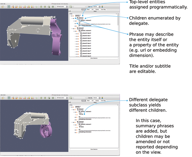
Figure 5. SMTK automatically generates a user interface for any modeling operation so you can fully specify the modeling task graphically.
Interfacing with VTK and Qt
You can use SMTK to develop applications to customize presentation of and interaction with geometric models. In Figure 4, each screenshot shows a VTK-based 3D rendering of a model, as well as a Qt-based tree view of the model entities and their relationships. You can customize both the VTK-based 3D rendering and the Qt-based tree view.
VTK Rendering of SMTK Models
In SMTK, each model entity—whether it is an edge, a face, or even a group—can have an associated tessellation that is used to display the model. There is a VTK source filter that, given an SMTK model manager and a model of interest, generates a multi-block dataset containing one vktPolyData object for each model entity owned by the specified model. You can color each block independently through vtkCompositePolyDataMapper. Since VTK provides a method for identifying which block is picked, identifying the selected model entity is simple. Arbitrary pipelines can then process the model geometry.
Be aware, however, that the tessellations produced by SMTK are not guaranteed to be conformal, unless the underlying model is discrete (not parametric). Many CAD packages provide non-watertight tessellations for rendering, as doing so is much faster than generating a conforming surface mesh.
Qt Model-View-Controller Presentation
SMTK contains several classes to help you present various model perspectives. The images in Figures 4 and 6 show the default, which is a tree of model entities whose children (also entities) form their boundaries in the next-lower dimension. There are circumstances, however, where you may want to only show entities of a given dimension or to show parent-child relationships other than boundaries. For instance, since SMTK allows you to attach an integer, a floating-point, and/or string properties to each model entity, you can show entities at the top of the tree and their properties as children. Use cases include the following:
- a tree view that shows model entities, allowing you to select entities when they are obscured in a 3D rendering by other geometry (e.g., a face inside a cavity);
- a tree view that shows model entities, allowing you to select entities when they are not being illustrated (e.g., shell-oriented uses that are not explicitly rendered and are associated with boundary conditions, rather than faces, in some multi-physics simulations);
- a list view that displays group membership and supports drag-and-drop modifications;
- a tree view that illustrates relationships between entities, sizing functions, and/or feature definitions used to constrain meshers; and
- a list view that shows entities ordered by their intersection points along a ray fired through a rendered view.
(The latter is for selection of entities as input to operations or for association with simulation attributes.)
Instead of writing a separate model or widget for each use case, SMTK has a framework that can express any of these cases. The framework consists of two base classes, DescriptivePhrase and SubphraseGenerator, plus some subclasses of each. The base classes are not tied to any particular user interface library. As a result, you can use them in both desktop and Web applications. If Qt support is enabled, SMTK also provides a subclass of QAbstractItemModel that uses DescriptivePhrase and SubphraseGenerator.
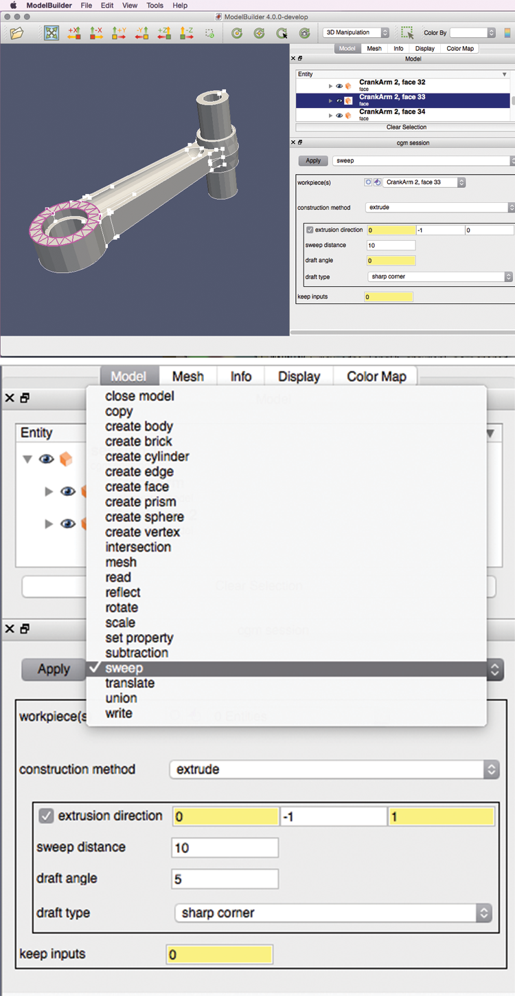
Figure 6. SMTK provides a flexible framework for presenting model entities and their properties in a tree view.
Conclusion and Acknowledgement
This article provides a brief overview of SMTK. For more information on the toolkit, please visit SMTK’s page on CMB’s website [4]. For questions, please refer to the SMTK mailing list [10].
In addition to STMK, CMB includes Remote Meshing Utilities (ReMUs), a library that provides the infrastructure to address variations in mesh requirements for computational simulations, as well as RGG and ModelBuilder. RGG is an open-source graphical user interface (GUI) tool that encapsulates the workflow of creating reactor core geometries for computational analyses, and ModelBuilder is a general-purpose tool for refining and developing input models for computational simulations.
This material is based upon work supported by the Department of Energy under Award Number DE-SC0007615.
This report was prepared as an account of work sponsored by an agency of the United States Government. Neither the United States Government nor any agency thereof, nor any of their employees, makes any warranty, express or implied, or assumes any legal liability or responsibility for the accuracy, completeness, or usefulness of any information, apparatus, product, or process disclosed, or represents that its use would not infringe privately owned rights. Reference herein to any specific commercial product, process, or service by trade name, trademark, manufacturer, or otherwise does not necessarily constitute or imply its endorsement, recommendation, or favoring by the United States Government or any agency thereof. The views and opinions of authors expressed herein do not necessarily state or reflect those of the United States Government or any agency thereof.
References
[1] Kitware, Inc. “ParaView Catalyst for In situ Analysis.” ParaView. http://www.paraview.org/in-situ.
[2] Sandia National Laboratories. “CUBIT.” CUBIT Geometry and Mesh Generation Toolkit. https://cubit.sandia.gov.
[3] Kitware, Inc. “Introducing the Computational Model Builder.” CMB. http://www.computationalmodelbuilder.org.
[4] B. O’Bara, D. Thompson, A. Bauer, Y. Yuan, J. Tourtetllot, and R. Maynard. “Meeting Pre-Processing Needs of Numerical Simulations.” Kitware Source, no. 34, 2015, pp. 10-13.
[5] Kitware, Inc. “Simulation Modeling Toolkit,” CMB. http://www.computationalmodelbuilder.org/smtk.
[6] Kitware, Inc. “Welcome to VTK.” VTK. http://www.vtk.org.
[7] Kitware, Inc. “Welcome to ParaView.” ParaView. http://www.paraview.org.
[8] Kitware, Inc. “Reactor Geometry Generator.” CMB. http://www.computationalmodelbuilder.org/rgg.
[9] SIGMA. “Overview.” SIGMA Scalable Interfaces for Geometry and Mesh Based Applications. http://sigma.mcs.anl.gov.
[10] Mail-admin at public.kitware.com. “SMTK-developers.” http://public.kitware.com/mailman/listinfo/smtk-developers.

David Thompson is a research and development engineer at Kitware. His interests include conceptual design, solid modeling, computational simulation and visualization, and mechatronics.

Bob O’Bara is an Assistant Director of Scientific Computing at Kitware. His main areas of interest are geometric modeling, mesh generation, model and mesh visualization, and general scientific visualization techniques.

Yumin Yuan is a research and development engineer on the Scientific Computing team at Kitware. He is the main software architect of the suite of CMB applications that regard geometric modeling, meshing, pre- and post-simulation analysis, and visualization.