Image-Guided Interventions Tutorial with IGSTK

The Image-Guided Surgery Toolkit (www.igstk.org) is a free, open-source toolkit that provides a framework for the development of image-guidance applications. In addition to providing an infrastructure, one of its goals is to serve as an educational resource for training newcomers to the field [1]. While this has been one of our goals from the beginning, the toolkit itself does not address it per se. Most often, newcomers find it intimidating to implement a brand new program using the toolkit components. To ease the burden, the toolkit includes several example applications. Most users prefer to start their development by modifying these examples. While this is helpful for application developers, these programs are not appropriate for teaching common concepts in image-guided interventions (IGI).
Our goal in this tutorial was to provide a set of programs that allow students to gain hands-on experience with IGI, enhancing their understanding of theoretical concepts. When teaching IGI, we describe algorithms based on mathematical models of the physical world. Students understand the models, can reiterate the derivations, but often do not seem to connect the models with the real world. For example, the fact that Fiducial Registration Error (FRE) does not reflect the quality of registration in paired point rigid registration is understood. But, when a student sees it happen with a navigation system in the physical world, there is an “Aha!” Moment. It is these moments that solidify their understanding of the theoretical concepts. Theory has been validated by practice. This tutorial was developed with the intention of eliciting these “Aha!” Moments.
Finally, in an era of rising higher education costs, we were resolved to provide an accessible tutorial with minimal cost to the users.
Accessibility
Two hurdles stood between us and providing a tutorial that is accessible to a wide audience; the cost and availability of imaging and tracking devices, key components required by many IGI systems. To address the former issue, we followed the example of Pace et al. [2]. We too provide CT scans of a simple LEGO phantom. Given that LEGO blocks are manufactured in a consistent manner, the scans can be readily used once the user builds the corresponding phantom.
To address the second issue, we realized that our initial observation that low cost tracking systems are not widely-available is mistaken. These types of systems are all around us. If you are reading this article on your laptop, then most likely you are staring directly at a tracking device: your computer’s webcam. All we have to do is calibrate these consumer-grade cameras to transform them into monocular tracking devices. Figure 1 shows two tracking devices that represent the opposite extremes of optical tracking, as compared using a variety of evaluation measures (i.e. accuracy, cost, refresh rate, etc.): a consumer grade webcam and a high end tracking system.
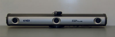
Figure 1: The two extremes of optical tracking, a webcam, QuickCam Pro 9000 from Logitech Inc., and the Optotrack Certus from Northern Digital Inc.
In the context of the Image-Guided Surgery Toolkit, all tracking devices are used in a similar manner with the only difference being in the initialization code, as illustrated by the following code snippets.
Initialization of the webcam based tracker:
/* Instantiate the tracker */
igstk::ArucoTracker::Pointer tracker;
tracker = igstk::ArucoTracker::New();
/* Setup tracker */
tracker->SetCameraParametersFromYAMLFile
(cameraCalibrationFile);
tracker->SetMarkerSize(50);
/* Instantiation and setup of tracker tool */
igstk::ArucoTrackerTool::Pointer trackerTool =
igstk::ArucoTrackerTool::New();
trackerTool->RequestSetMarkerName(“102”);
/* Common code {*/
/* Frequency setting and opening communication */
tracker->RequestSetFrequency(30);
tracker->RequestOpen();
/* Tracker tool configuration, tracker attachment
and start tracking */
trackerTool->RequestConfigure();
trackerTool->RequestAttachToTracker( tracker );
tracker->RequestStartTracking();
/* } common code*/
Or the equivalent for the NDI Certus tracker:
/* Instantiate the tracker */
igstk::NDICertusTracker::Pointer tracker;
tracker = igstk::NDICertusTracker::New();
/* Setup tracker */
tracker->SetIniFileName(CertusSetupFile.c_str());
tracker->rigidBodyStatus.lnRigidBodies = 1;
tracker->rigidBodyDescrArray[0].lnStartMarker = 1;
tracker->rigidBodyDescrArray[0].lnNumberOfMarkers = 4;
strcpy(tracker->rigidBodyDescrArray[0].szName,
rigidBodyFile.c_str());
/* Instantiation and setup of tracker tool */
igstk::NDICertusTrackerTool::Pointer trackerTool =
igstk::NDICertusTrackerTool::New();
trackerTool->RequestSetRigidBodyName
(rigidBodyFile.c_str());
/* Common code above */
Tutorial Structure
Our tutorial is comprised of a set of programs allowing the user to carry out a simulated biopsy procedure using a needle-like tool. The end goal is to provide guidance so that the needle tip is inserted to the desired target point inside the “body,” without going through critical structures. In many aspects, this procedure is an advanced version of the children’s game “Operation” (http://www.hasbro.com/games/en_US/operation/?page=history).
The tutorial programs are built using IGSTK and Qt, with the software architecture shown in Figure 2. To carry out the biopsy procedure the user performs setup and system calibration, procedure planning, and navigation, as described in the following sections.
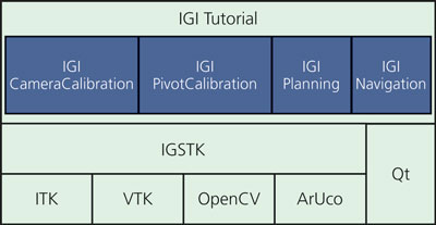
Figure 2: IGI-tutorial software architecture
Setup and Calibration
This component is specific to our tutorial as most actions are not required or desired in clinical practice. Initially, the user has to build the phantom, print calibration and tracking patterns, and construct a tracked pointer tool. The camera is then transformed into a tracking system using the provided calibration software. Finally, the pointer tool is calibrated; that is, the location of the tool tip relative to the attached marker is estimated.
The software components used in this logical step are:
IGICameraCalibration: This application is used to calibrate the camera in order to use it as a tracking device. After calibration there is a calibration quality assessment or validation step. A pattern with known distances is detected and the estimated distance is overlaid onto the pattern’s image.
IGIPivotCalibration: This application is used to calibrate a pointer tool in order to track the tool tip.
Planning
The preoperative planning software allows the user to specify the system setup, and identify registration fiducials and target points in the CT. The software component used in this step is the IGIPlanning program.
The user first selects the image dataset and the camera and pointer calibration files. Then, tracking setup is performed by selecting the marker used for the dynamic reference frame (DRF), the pointer tool, and additional arbitrary tools that will be displayed in the navigation’s 3D view. The DRF is then rigidly attached to the phantom, allowing us to freely move the phantom during the navigation phase as all measurements will be relative to this coordinate frame which maintains its relationship with the phantom. Finally, the user identifies registration fiducials and target points by scrolling through the volumetric dataset, which is displayed using the standard radiological reformatted views. Figure 3 shows the user interface for selecting the tracked markers and the fiducials.
Figure 3: Planning interface. On left, user interface for tracker setup. On right, multiplanar views showing the image dataset with the registration fiducials overlaid as yellow spheres.
Navigation
The software component used in this step is the IGINavigation program. This application displays standard radiological views with the displayed planes corresponding to the location of the tracked pointer tool’s tip.
To perform navigation, the user loads the configuration file generated in the planning phase. Next, they need to perform paired point rigid registration. At this point, we already have the fiducial locations in image space, so we need to identify the corresponding points in the physical space, which are obtained with the tracked pointer tool. Lastly, the two point sets are registered and the user can start navigating. The navigation display shows axial, sagittal, and coronal planes corresponding to the pointer tool’s tip location.
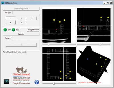
Figure 4: Navigation software. Yellow spheres represent registration fiducials. Red sphere represents the target. Cross-hairs follow the tooltip (tool tip is on the defined target in physical world) and reslices the planes accordingly.
The quantity describing the root mean square error of the fiducial locations after registration, the Fiducial Registration Error (FRE), is reported immediately after registration. Clinically this is irrelevant as we are interested in the error at the target locations, the Target Registration Error (TRE). During planning, the user can select a target in the program’s interface and the distance between that and the actual target defined in the image; the current visualized tip position according to the tool tip position in the physical space is displayed. Figure 4 shows the program during navigation.
Having given a general description of the tutorial, the following sections proivde two examples of using it to enhance the students’ learning experience.
Examples of “Aha!” Moments
FRE does not reflect TRE
In solving the paired point rigid registration problem the registration algorithm finds the transformation that best aligns the two point sets in a least squares sense. The quality of the alignment with regard to the points used for registration is given by the FRE. The quantity we are actually interested in is the TRE, which is uncorrelated with FRE [3]. To drive this point home, we have the students perform registration twice: once with the phantom constructed correctly, and then with a shifted fiducial configuration. In both cases both FRE and TRE are estimated. Figure 5 shows results from this experiment, exhibiting considerable changes in TRE even though there is minimal change in FRE.
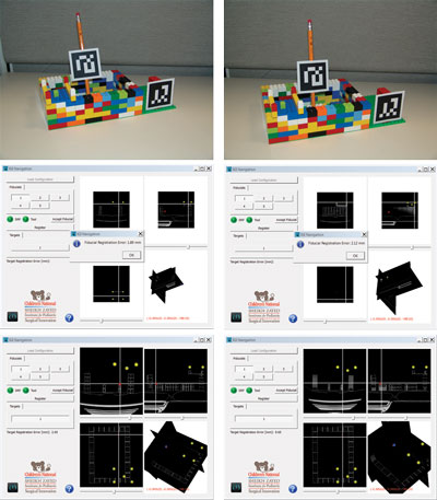
Figure 5: On the left we have a correctly (corresponds to the CT data) constructed phantom, resulting in a FRE of 1.89mm and TRE of 2.05mm. On the right, the fiducial configuration is shifted one step from the correct location. The FRE is 2.12mm, very similar to that obtained for the correct configuration. On the other hand, the TRE is 9.65mm, exhibiting the difference between the CT data and the physical world.
The effect of rotational errors on point location (lever effect)
The effect of rotational errors on point location is dependent upon the distance of the point from the center of rotation. This is often referred to as the “lever effect:” the closer the point is to the origin, the less it is affected by the rotational errors. This is illustrated by the pivot calibration procedure used to estimate the tip of a pointer tool relative to a tracked marker.
When performing pivot calibration, the pointer is pivoted and rotated while keeping its tip at a fixed location. The marker’s poses are used to estimate the tip location using a linear least squares approach. Due to the lever effect, calculating the tip offset from the marker origin is less accurate the larger the distance is between the two. To drive this point home, we have the students perform pivot calibration twice, once with the marker close to the tip, and once far from it. The calibration software reports the root mean square error which reflects the tip estimation error. Figure 6 shows results from this experiment, exhibiting a larger error for the larger distance.
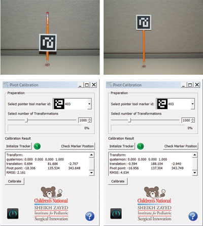
Figure 6: Effect of distance between the tracked marker’s origin and the pointer tip (a.k.a lever effect) on accuracy.
The shorter distance results in a RMS of 2.16mm vs. the 4.03mm for the longer one.
Conclusions
We have described a hands-on tutorial for illustrating various concepts in image-guided interventions. This educational tool is intended to enhance the understanding of theoretical concepts taught in class. Download the tutorial from:
http://public.kitware.com/IGSTKWIKI/index.php/IGI_Tutorial
References
[1] “IGSTK: Building High Quality Roads with Open Source Software”, L. Ibanez, A. Enquobahrie, M. Turek, J. Jomier, R. Avila, P. Cheng, Z. Yaniv, F. Lindseth, K. Gary, K. Cleary, Workshop on Systems and Architecture for Computer Assisted Intervention in conjunction with MICCAI, 2008.
[2] D. F. Pace, R. Kikinis, and N. Hata, “An accessible, hands-on tutorial system for image-guided therapy and medical robotics using a robot and open-source software,” Open Science Workshop in conjunction with MICCAI, 2007.
[3] J. M. Fitzpatrick, “Fiducial registration error and target registration error are uncorrelated”, SPIE Medical Imaging: Visualization, Image-Guided Procedures, and Modeling, 2009.
 Özgür Güler is a post-doctoral fellow at Children’s National Medical Center. His research interests include development, assessment and application of image guided surgery systems, medical image processing, medical registration and registration error assessment, and software development. He is one of the primay developers of the Image-Guided Surgery Toolkit.
 Ziv Yaniv is a principal investigator at the Sheikh Zayed Institute for Pediatric Surgical Innovation, Children’s National Medical Center. His main areas of interest are image-guided interventions, medical image analysis, computer vision, and software engineering. He actively supports the development of open source software, and is one of the lead developers of the free open source Image-Guided Surgery Toolkit and a contributor to the Insight Registration and Segmentation toolkit (ITK).