3D Printing Adapter to fit Raspberry Pi Camera to Microscope
One of the typical uses of 3D printers is to create objects that can not be found in the market. For example, objects whose shapes are so specific that few people would be interested in them, and therefore, manufacturers would not find them profitable to produce.
Adapters fall neatly into this category. They are pieces designed to attach two devices that were not originally built to fit together.
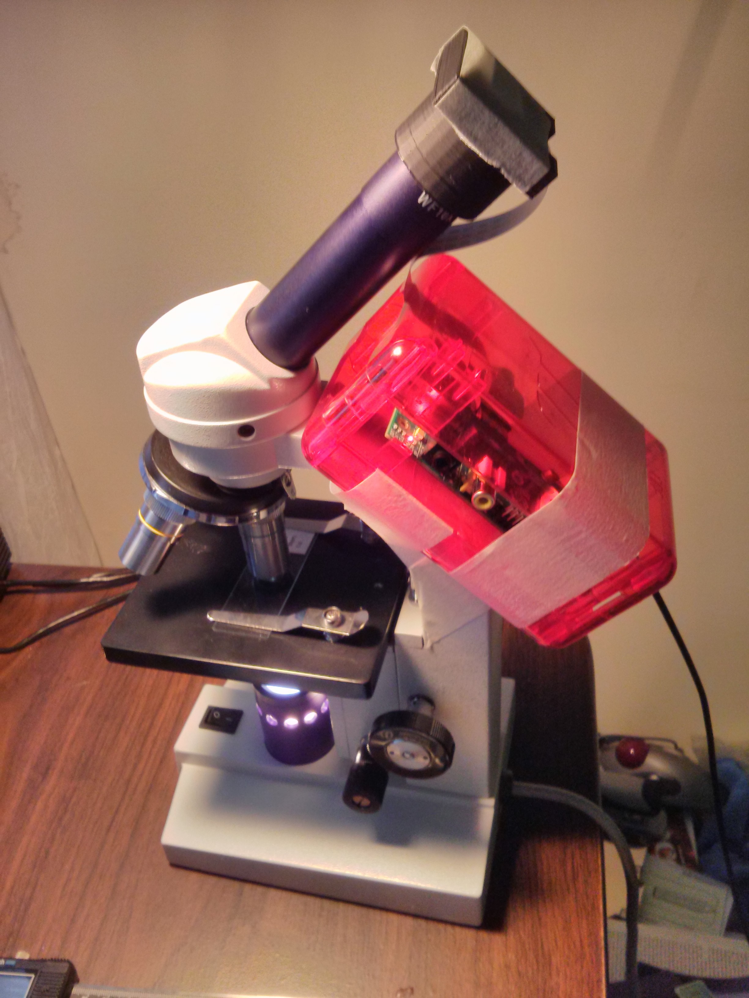
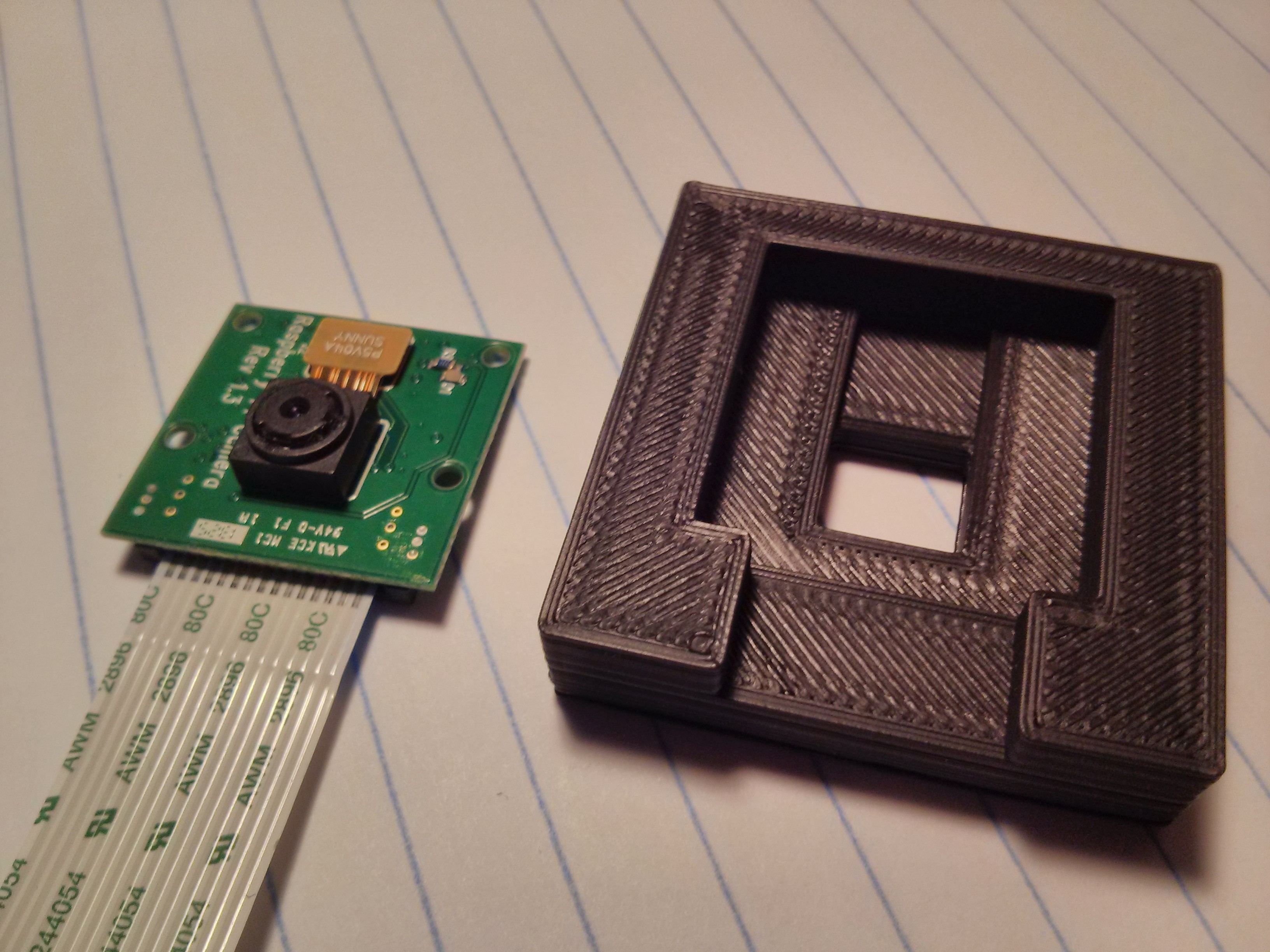
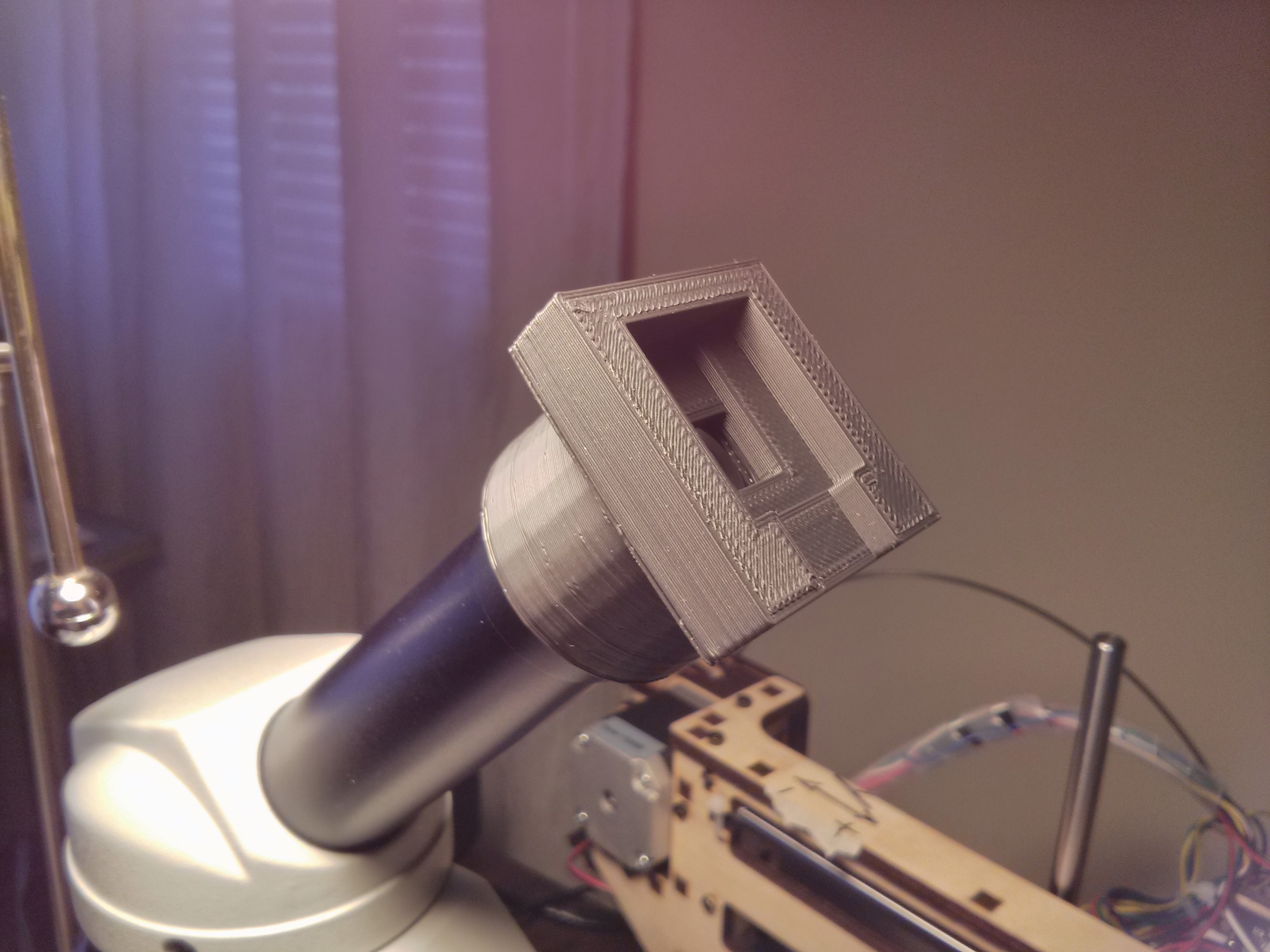
Using our now functioning Printrbot Simple 3D Printer, here we designed, printed and tested a simple adapter to fit the Camera of the Raspberry Pi to a small low-cost Microscope.
 |
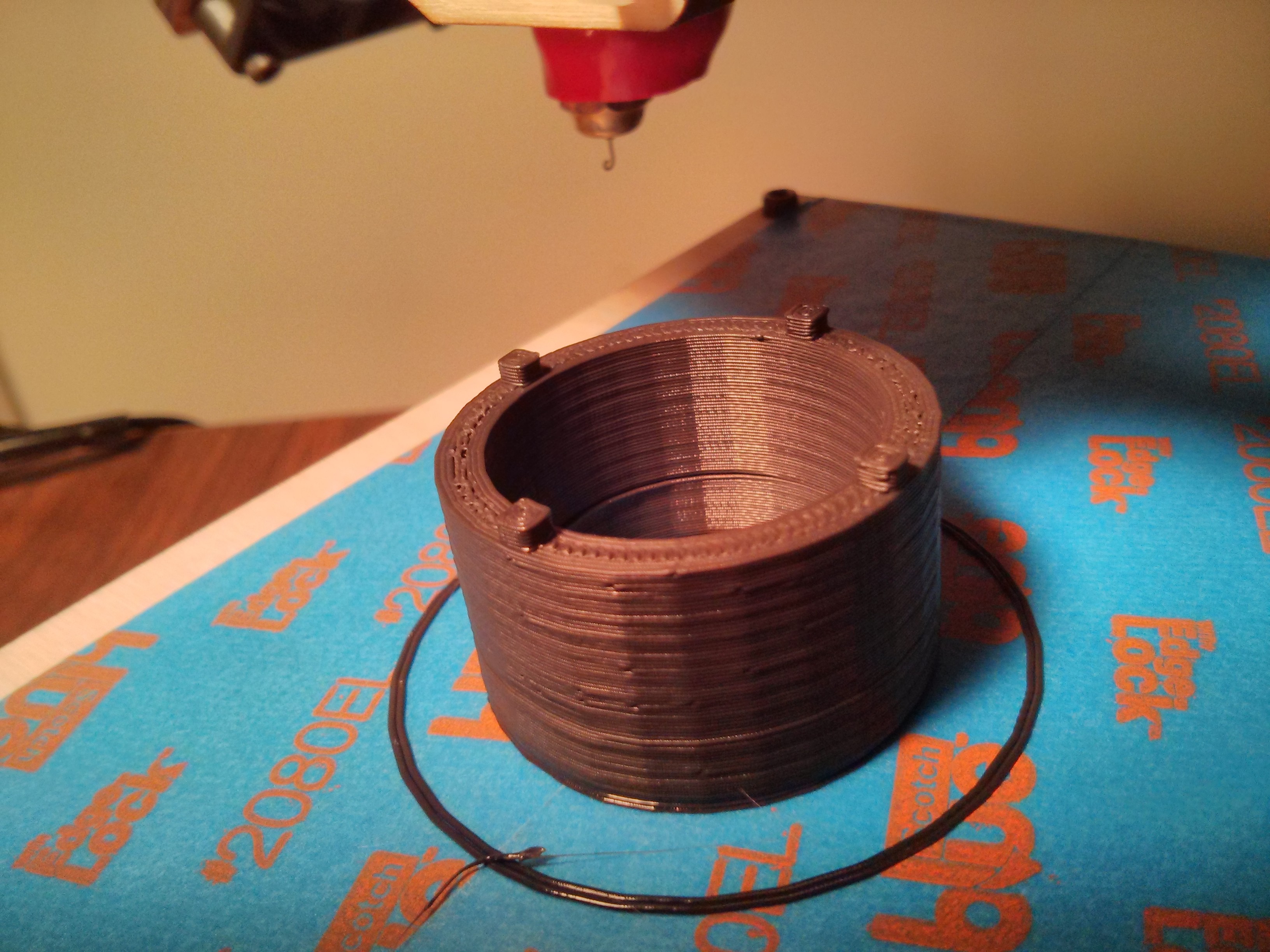
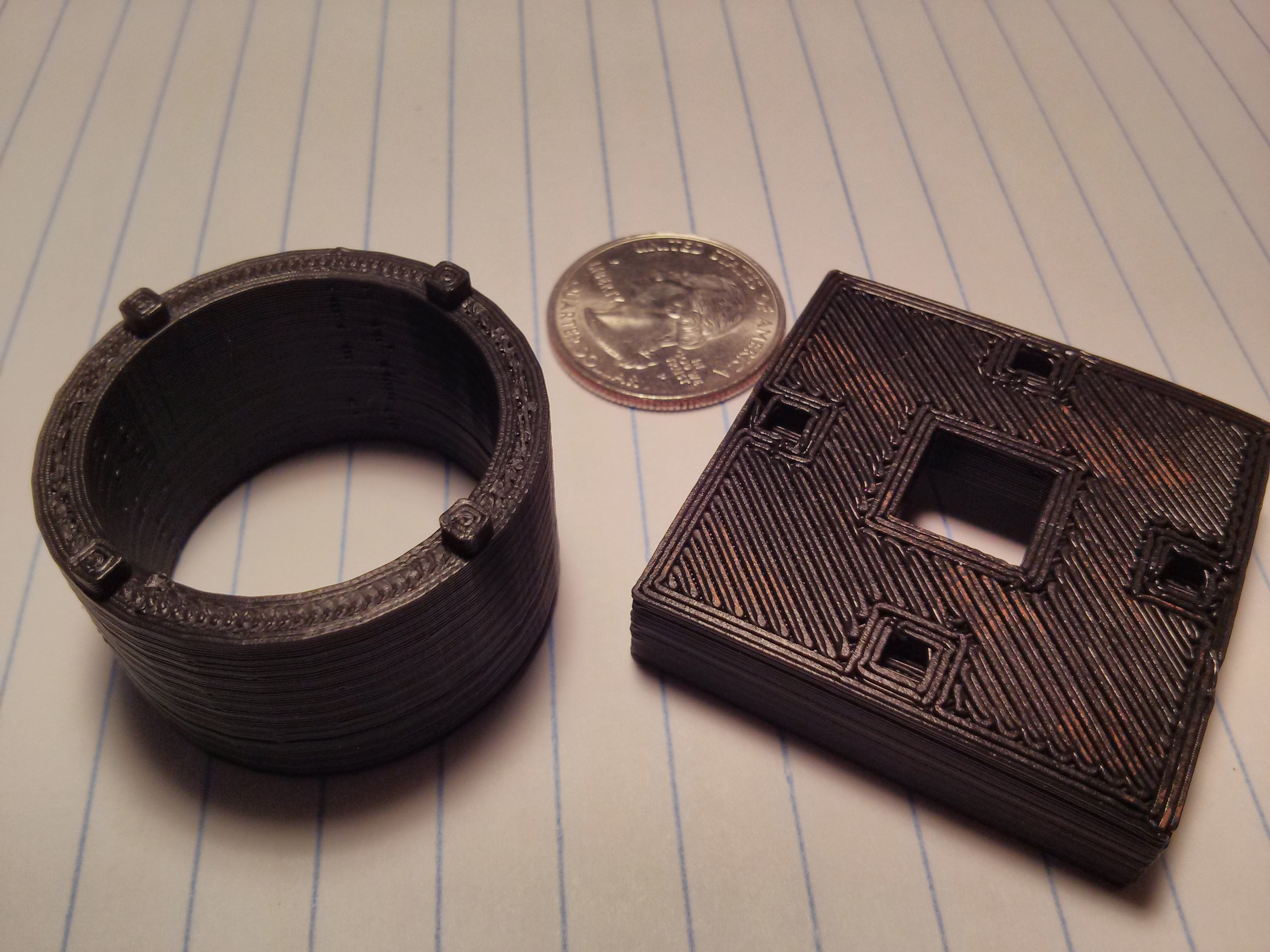
The pieces were
- Designed using the open source program OpenSCAD, and then
- Printed using Repetier (also open source) to drive the Printrbot Simple Printer.
 |
 |
 |
 |
 |
 |
 |
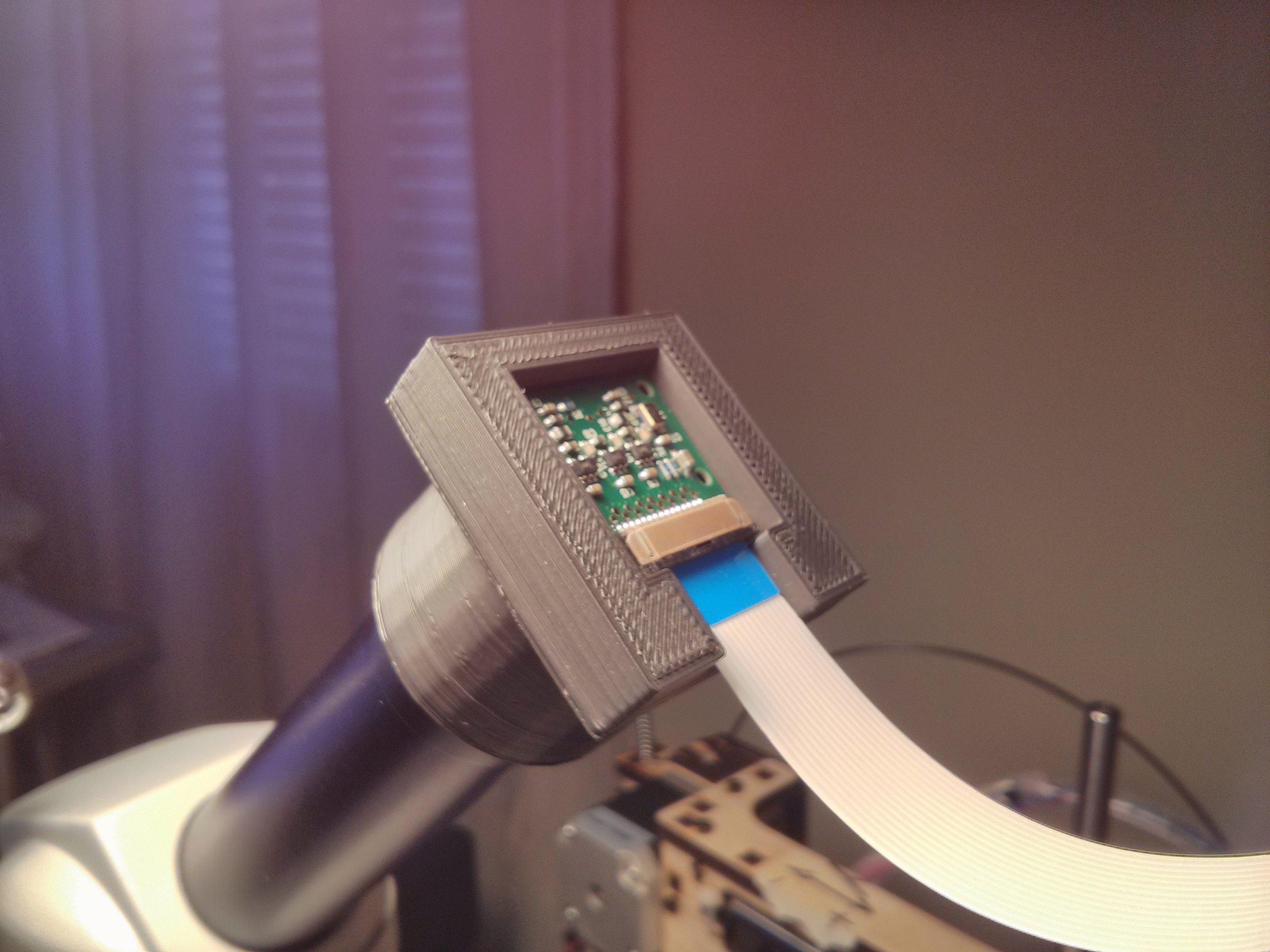 |
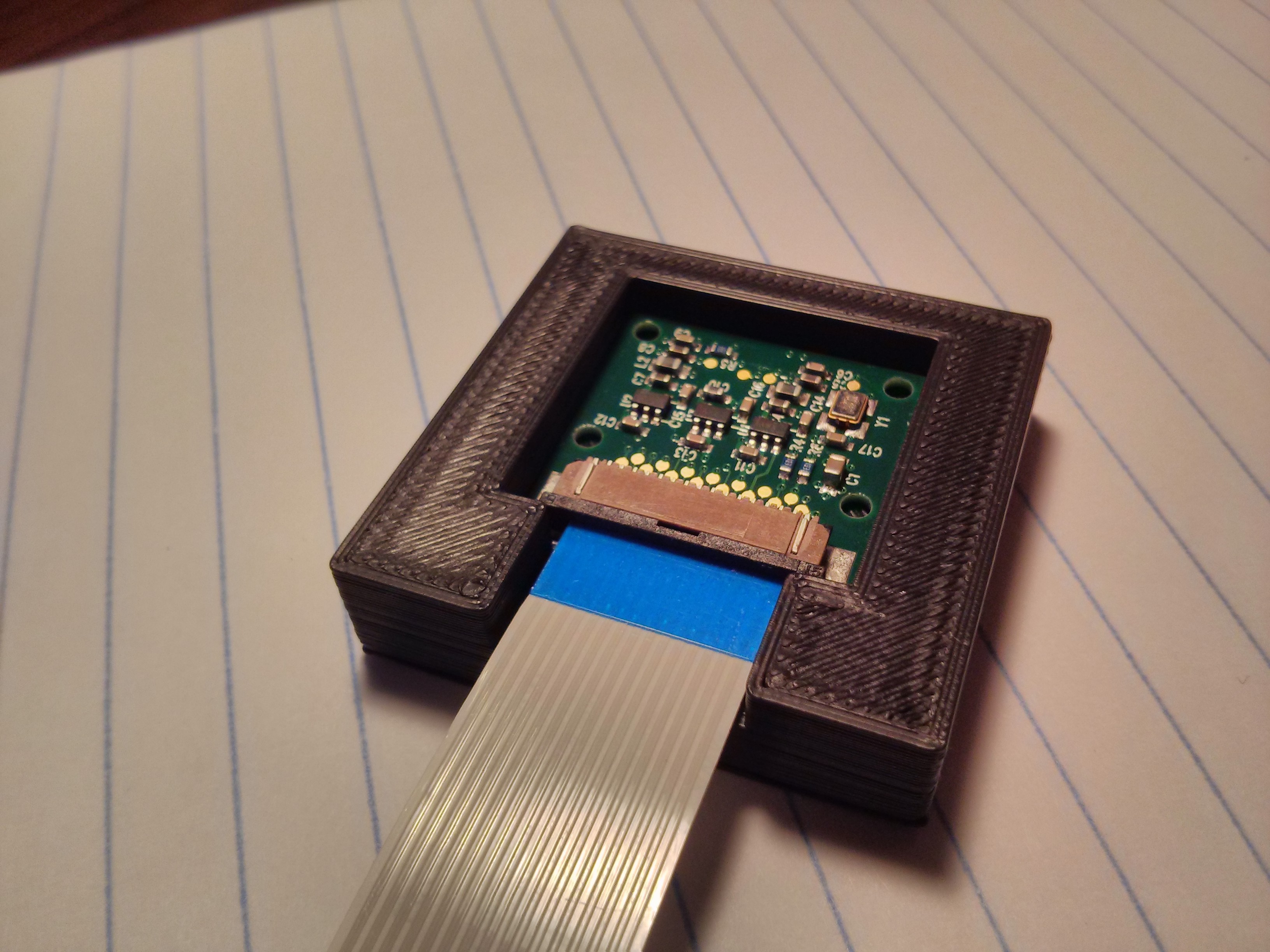
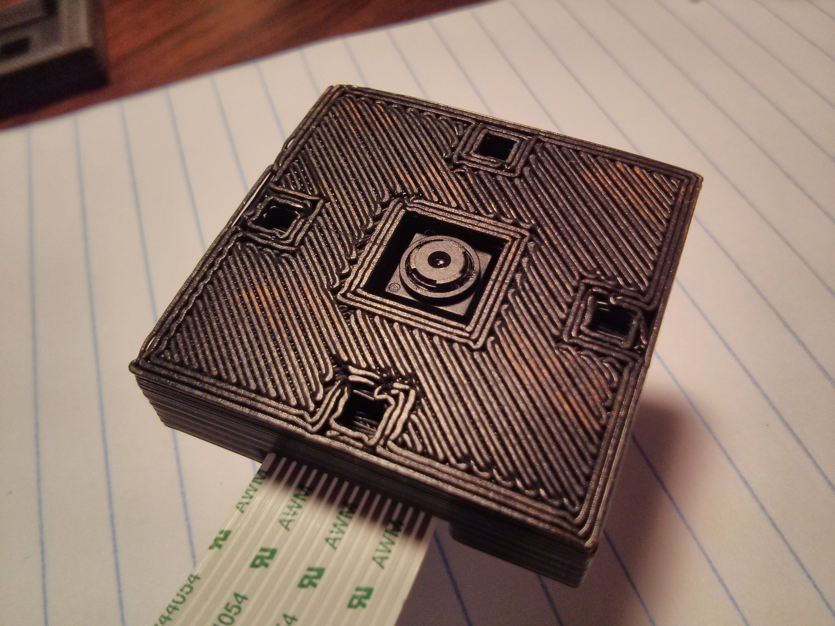
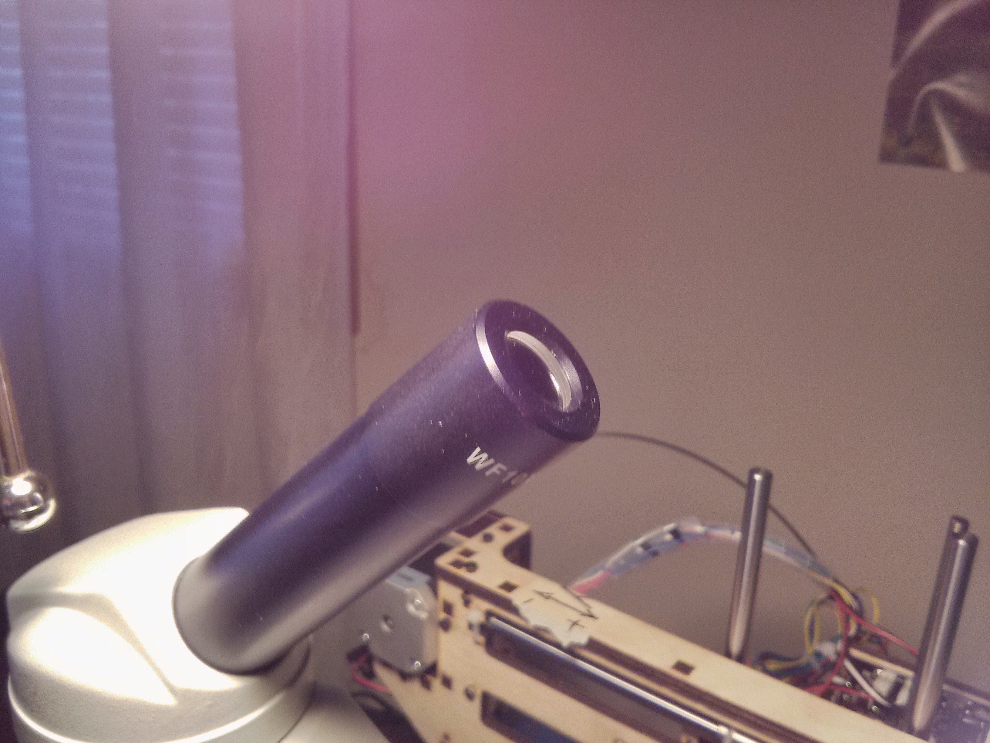
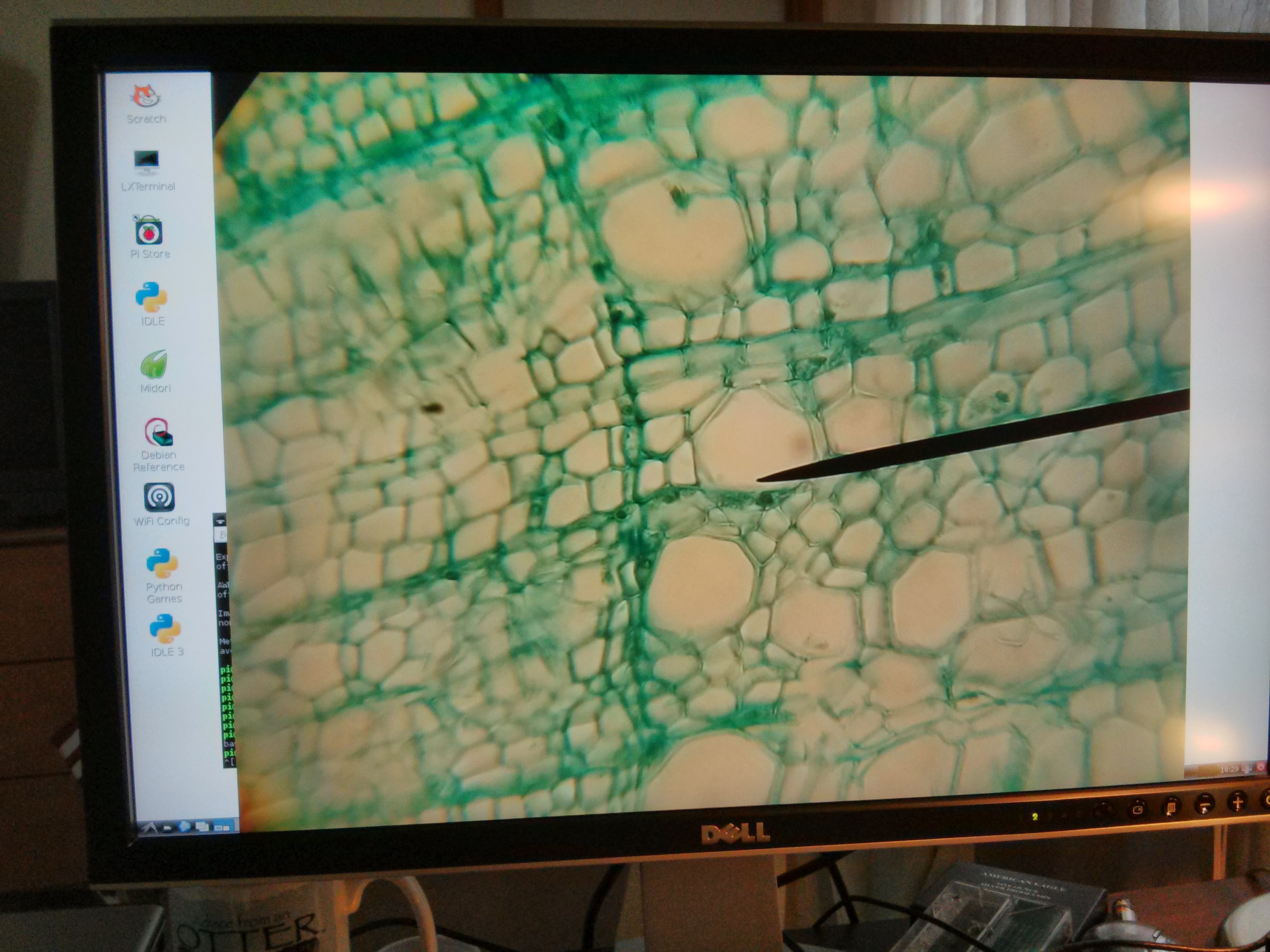
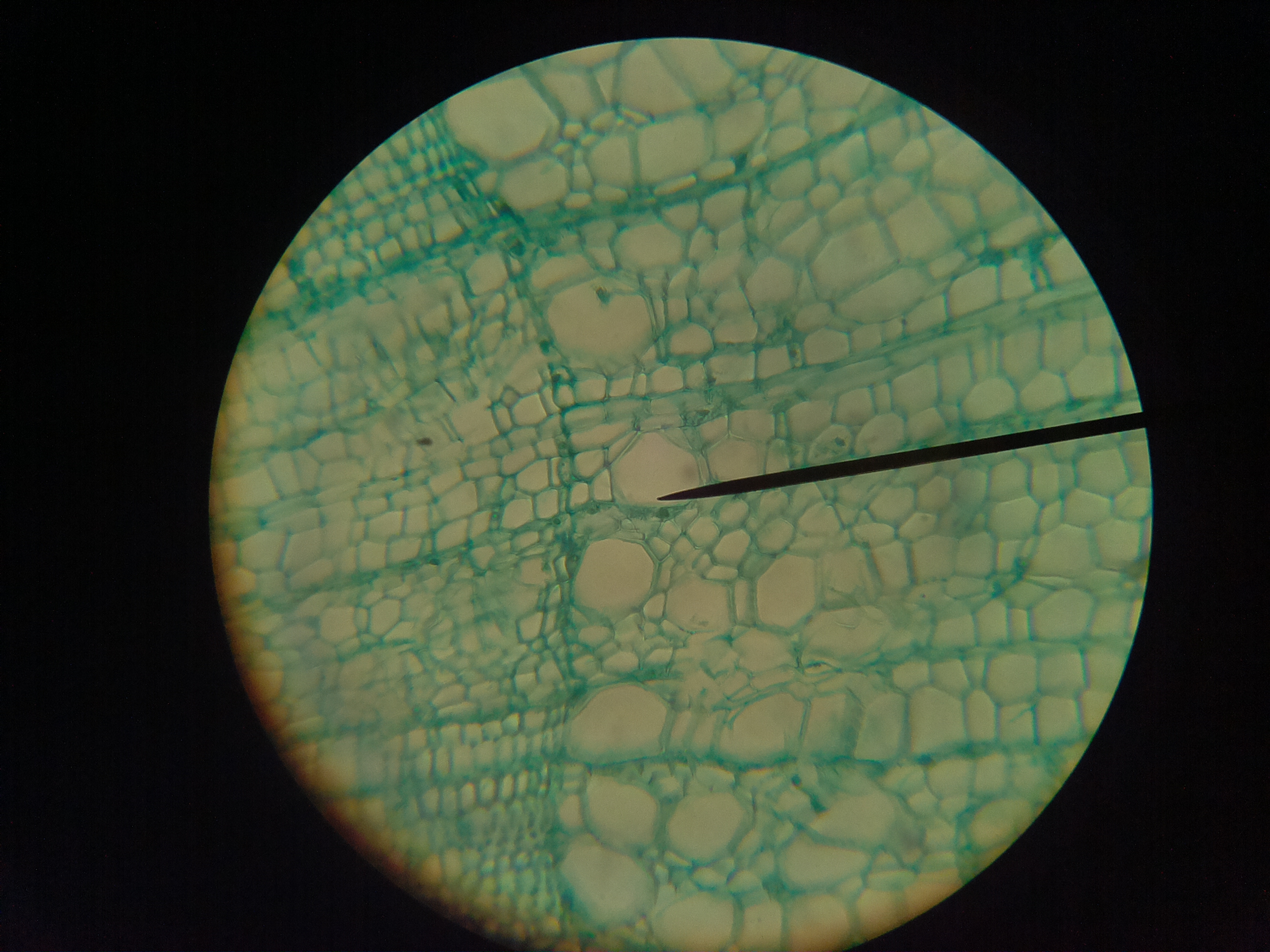
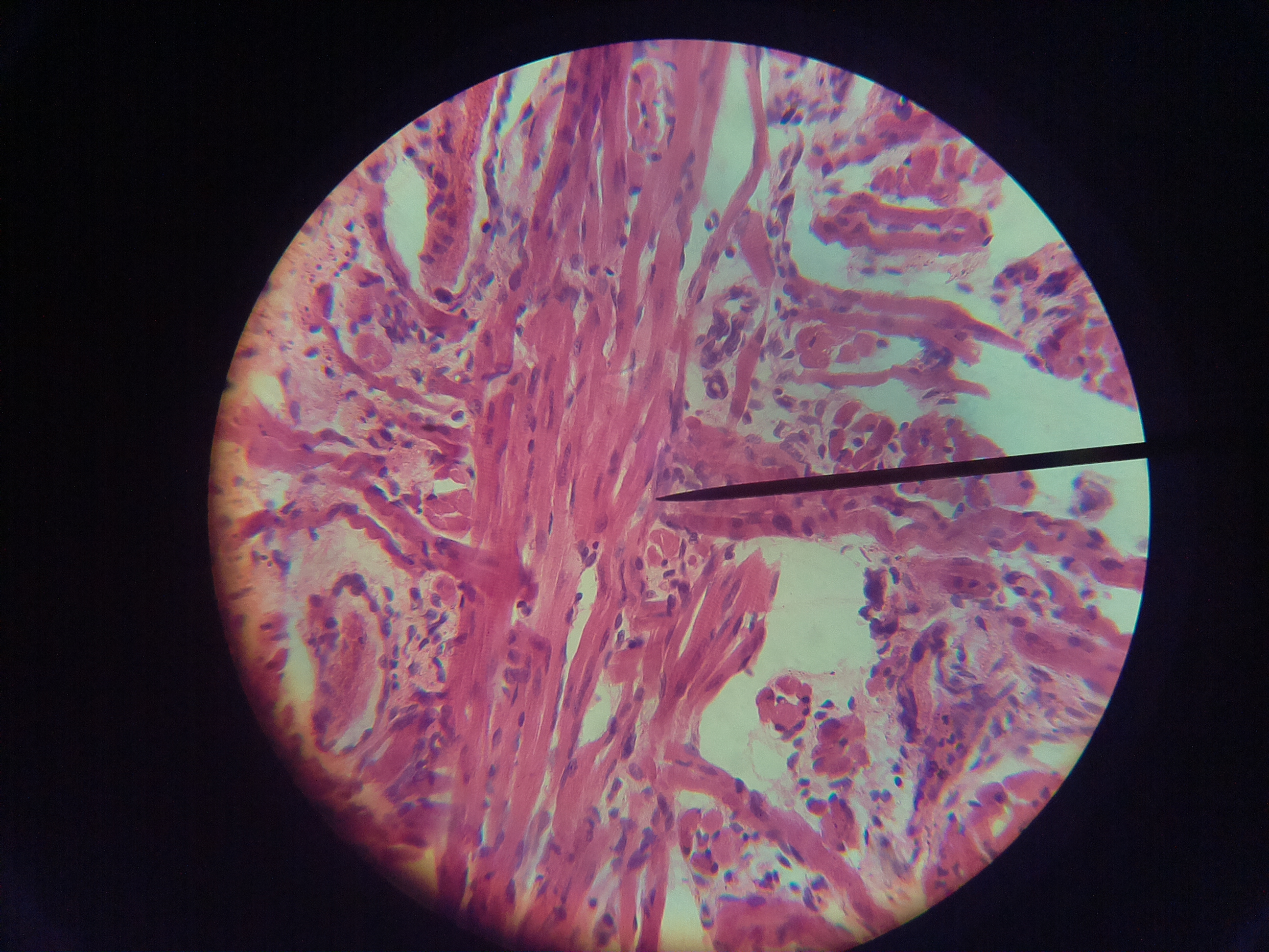
The position of the adapter was adjusted to place the Pi Camera at the location where it could take the maximum field of view. At that point the following images were acquired with Raspistill directly from the Raspberry Pi.
 |
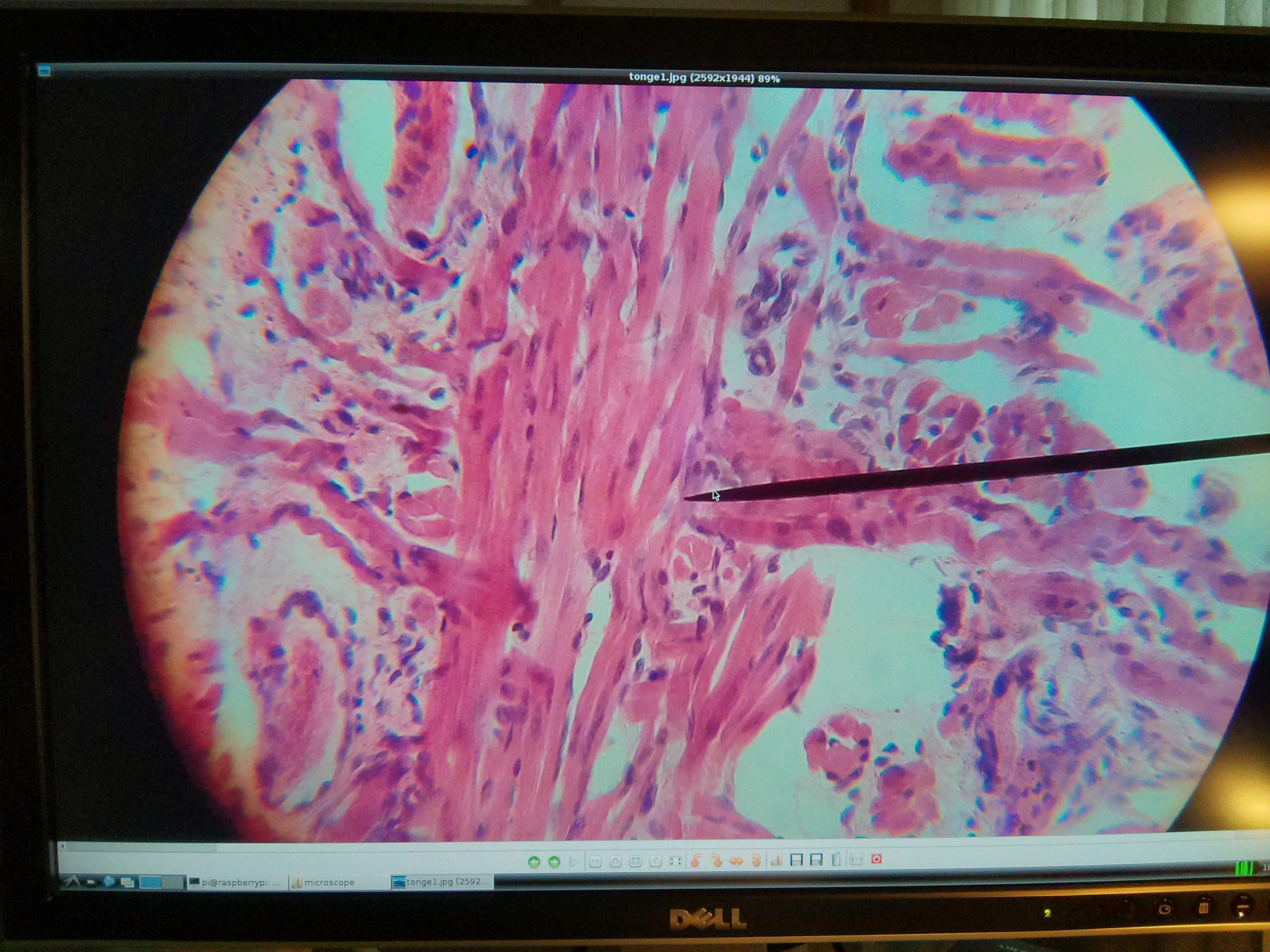 |
The 2592 x 1944 pixels images in the Pi Camera:
 |
 |
Following the sharing tradition of the Maker community:
- The OpenSCAD designs are available in Github
- As well as the STL files with the two parts
Note that Github is now rendering STL files in place, and is also displaying diffs of STL files.
To experience time-travel in Github: click on the “Revision Slider” button under the image and a slider will appear at the top of the image. Moving the slider will show the different stages of the STL shape across time.
The design and models or the adapter are also available in Thingiverse here,
under the Creative Commons by Attribution 4.0 License.
Hi Luis,
Just an FYI, the board opening is a tiny bit too small for my pi camera. I printed the part and I can almost – but not quite – fit the camera board into the part. I’ll have to widen the outer rectangle to make it fit.
-Scott
PS.
I should note that I did modify the part to fit my microscope’s larger eye piece. I did not touch the board opening dims, but it’s still possible I messed things up on my end.
Hi Scott,
Thanks for sharing your experience.
I went through a couple of iterations with the Pi Camera opening, and end up adding a tolerance factor. It is the “clearance” variable in in line 43 of the OpenSCAD file:
https://github.com/luisibanez/ShapesFor3DPrinting/blob/master/OpenSCAD/piCameraMicroscopeAdapter.scad#L43
I set the clearance to 1mm, to get the opening to be OK in size for the Pi camera, which is 8mm x 8mm (as far as I was able to measure with calipers).
In the last print, when printing on PLA in the Printrbot Simple, the opening turned out to be too large (we could trim half a millimeter). Looking back, it may well be that our Printrbot is not fully calibrated though…
You may want to fiddle a bit with the “clearance” parameter. I’ll be curious about the material that you are using to print (PLA/ABS), and the type of printer you are using as well.
I’m about to do the adapter for a Telescope eyepiece (line 49)
https://github.com/luisibanez/ShapesFor3DPrinting/blob/master/OpenSCAD/piCameraMicroscopeAdapter.scad#L49
I’m tempted to add openings for three screws, so that the tube can be aligned better with eyepiece.
Probably will also add a cover for the back of the Pi Camera adapter (which now is just left open), need to experiment a bit with angled slots first…
If you have a chance, it will be great if you could share some pictures in Thingiverse.
http://www.thingiverse.com/thing:214466
Thanks !
Luis
Hi Luis,
I think the problem is line 74. That cube is just slightly too small. So, instead of:
cube(size=[25,25,5], center=true);
I’m *guessing* something like the following would work:
cube(size=[27,25,5], center=true);
It is printed with PLA plastic. I’m not sure the printer (I ordered the part using makexyz – maybe someday I’ll have my own 3d printer 🙂
I’ll put some pics on thingiverse once I get things filed down so the board fits.
-Scott
Scott,
Thanks for clarifying. I thought you were referring to the camera housing, but you were talking about the actual board.
When measuring it with calipers, I got the board measures as 25mm x 24mm (with the camera bus cable going along the Y direction).
So, following your suggestion, I have now added a clearance in that direction:
https://github.com/luisibanez/ShapesFor3DPrinting/commit/421b565853d66ac033a24af87f5aa96ac3d1bc30#diff-182e05a7cb3ed616968031e71f1eb518R78
to be
cube(size=[25+c,24+c,5], center=true);
now in line 78:
https://github.com/luisibanez/ShapesFor3DPrinting/blob/master/OpenSCAD/piCameraMicroscopeAdapter.scad#L78
Github shows the changes in the STL file here:
https://github.com/luisibanez/ShapesFor3DPrinting/commit/c293f9dd70834158c00cfad11bf48feb60e83543
Also uploaded a new STL file to thingiverse.
http://www.thingiverse.com/download:407172
I’m now adding a back cover for the camera.
Hi Luis,
Thought I’d show you the first pic from my microscope with the raspberry pi camera: https://twitter.com/MonkScott/status/420335417817182208/photo/1
Obviously, it doesn’t fill the FOV, but still exciting!
-Scott
Hi Scott,
Very nice !
Thanks for sharing the picture.
I had a similar problem with the FOV. Solved it by sliding the microscope adapter tube away from the eyepiece by about 10mm. (The exact distance probably depends on the focal distance of the eyepiece).
Even at the best distance, couldn’t fill up the FOV of the Pi Camera, but got to maximize the area, and to get in focus the pupil around the image.
Holding the tube at that position, is indeed one of the reasons why I’m thinking on adding the three screws to adjust the 3D printed cylinder to the eyepiece. Something along the lines of what is used in finderscopes in telescopes (http://en.wikipedia.org/wiki/Finderscope).
Other ideas are welcome… 🙂
Thanks
Luis