Better Transparency with VTK and WebGPU
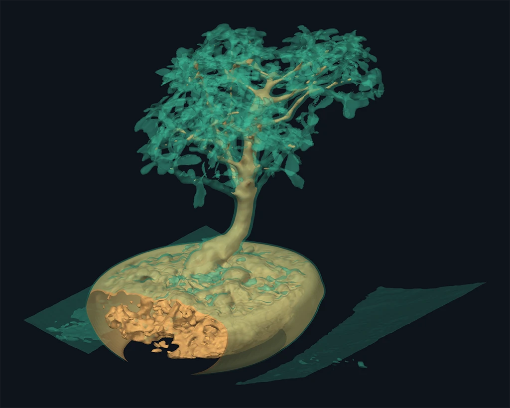
Transparency is a seemingly simple and powerful visualization technique to facilitate the understanding of complex geometric structures. However, to do so accurately, and at highly interactive frame rates, is challenging.
That is why we’re excited about VTK’s new WebGPU deep framebuffer. It collects translucent rendering fragments in one geometry pass, then composites them in depth order, preserving relationships that VTK’s default OpenGL transparency averages away. For nested scans and intersecting simulation surfaces, this gives us a clearer way to explore how the pieces fit together.
Transparency in VTK’s OpenGL backend
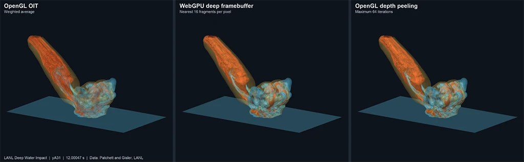
VTK’s OpenGL backend offers two approaches to order-independent transparency. The default, selected by UseOIT, accumulates an alpha-weighted average of the translucent colors and computes the combined opacity. It processes the geometry in one pass and uses a fixed set of image buffers. Because the color accumulation does not recover depth order, a fragment behind a surface can contribute as strongly as an equally transparent fragment in front of it. The result is stable under changes in drawing order, but can flatten the distinction between internal and external surfaces.
Depth peeling recovers that ordering. It renders the translucent geometry repeatedly, retaining the next layer at each pixel on each pass. VTK uses dual depth peeling when supported, collecting layers from both the front and the back of the depth range. An earlier post, VTK Technical Highlight: Dual Depth Peeling, explains the algorithm and its improvement over single depth peeling. That work was later extended to interleave translucent surfaces with volume rendering, as described in Rendering translucent geometry intermixed with volumes.
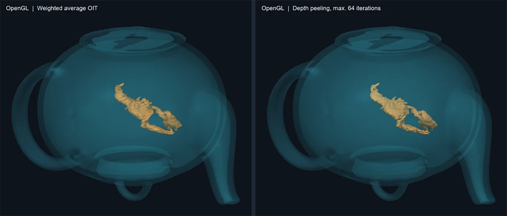
Weighted average OIT makes an image independent of drawing order, but that does not make the composition correct. Once depth has been discarded, averaging cannot distinguish a surface in front from the same surface behind. Peeling retains that distinction by revisiting the geometry for successive depth layers.
Preserving depth with the deep framebuffer
The WebGPU deep framebuffer records translucent fragment colors and depths in per-pixel lists. A later resolve sorts the retained fragments and composites them back to front over the opaque image. A surface in front attenuates the contribution behind it, as ordinary alpha composition requires. Weighted average OIT cannot recover this result in general because it has already discarded the fragments’ depth order.
The difference is visible even with two rectangles. In the top row below, red is in front; in the bottom row, blue is in front. Both layers have opacity 0.5. Exchanging their depths should change the overlap color.
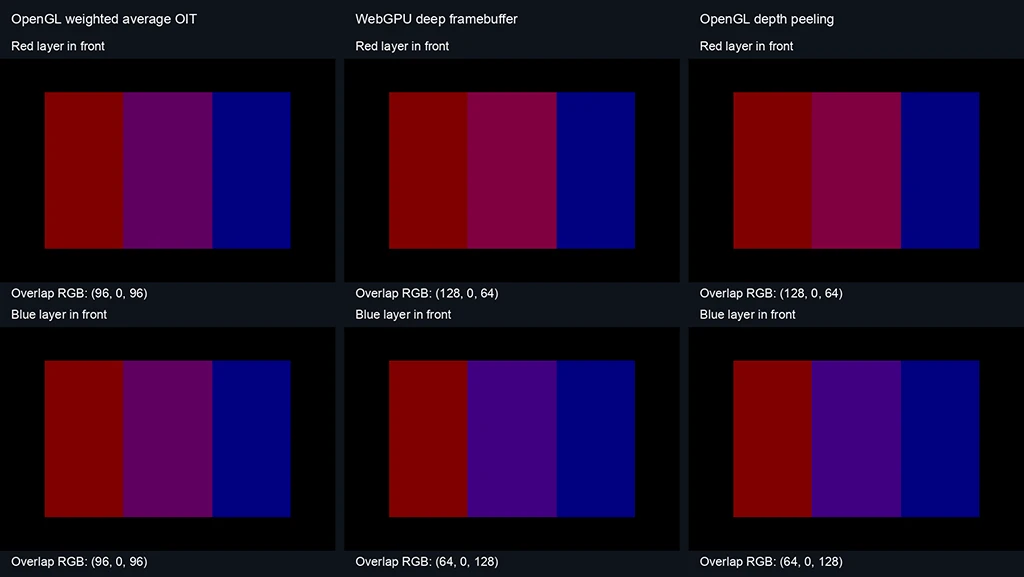
In a scientific scene, those layers may be an outer shell and an internal component, or two intersecting field surfaces. Preserving their depth order lets the nearer surface obscure the farther one by the intended amount. This is a concrete improvement in compositing over weighted average OIT: the renderer retains information that averaging loses.
The deep framebuffer also avoids peeling’s repeated geometry work. It records the translucent fragments in one geometry collection pass, using storage-buffer atomics available in core WebGPU, then resolves their lists in a full-screen pass. It spends memory and sorting work to recover depth order instead of rasterizing the geometry again for each peel.
The current resolve retains the nearest sixteen fragments per pixel. Extra fragments are omitted if that bound or the shared storage pool’s capacity is exceeded.
Examples: Seeing inside scientific data
Boston Teapot
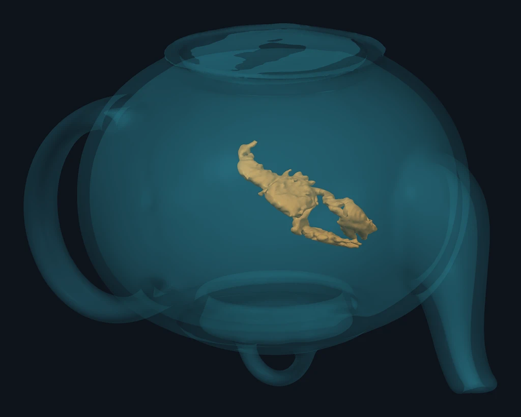
Bonsai
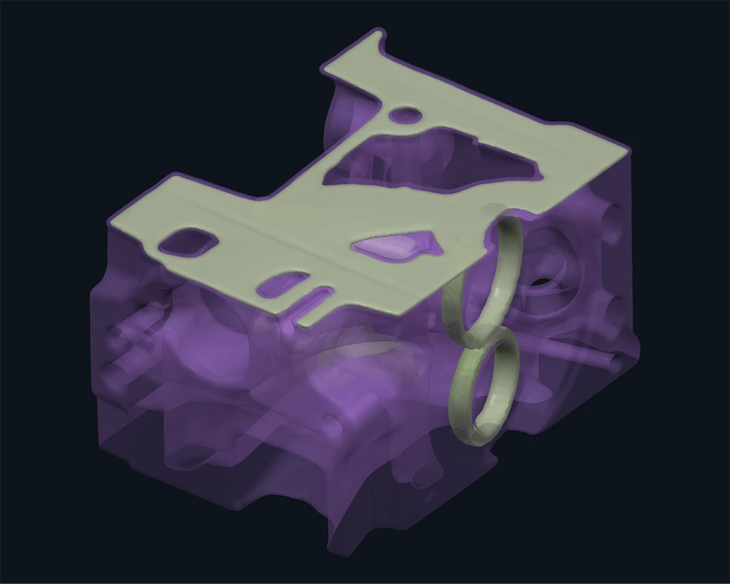
Engine
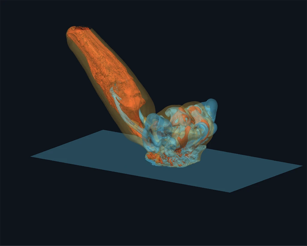
Overlapping fields in an asteroid ocean impact
The LANL Deep Water Impact dataset combines water volume fraction, temperature and asteroid volume fraction. In the plume and entry trail, the surfaces fold through one another. Sorting the three actors cannot establish the fragment order within those shapes.
The comparison below keeps the impact frame and viewing conditions fixed. It lets us examine how the three transparency methods handle those overlapping fields.
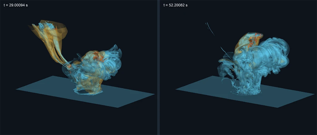
The later frames show how the water plume changes while the entry trail thins. The thresholds, colors, opacities, viewing direction, and orthographic framing stay fixed across this time sequence.
Changing the thresholds exposes a different set of contours in the same frame. The next pair keeps the time, orthographic view, colors and opacities fixed.
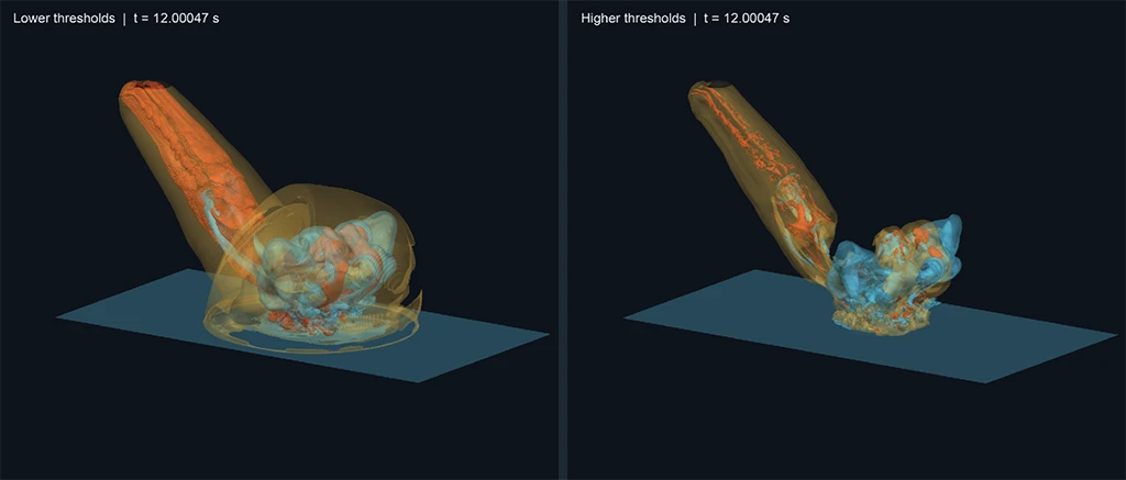
v02 = 0.1, tev = 0.035 eV, v03 = 0.01. Right: v02 = 0.9, tev = 0.2 eV, v03 = 0.5. Each color continues to identify the same field; the isovalues select the surfaces shown.Changing the viewing direction changes how those surfaces overlap in the image. The deep framebuffer establishes their order at each pixel from the new viewpoint.
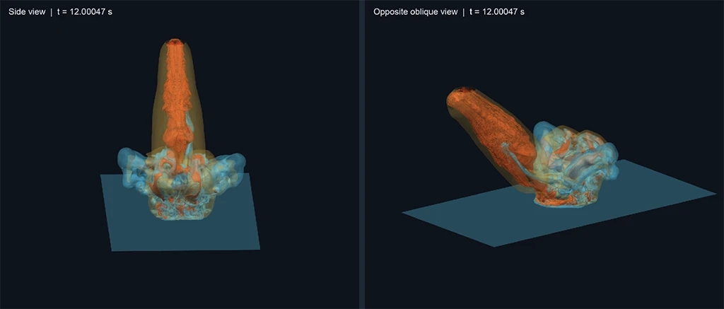
v02 = 0.5, tev = 0.09 eV and v03 = 0.1. Only the camera direction changes; the focal point, orthographic scale, geometry and material settings stay fixed.The publication captures share geometry, camera and materials within each method comparison. Reversing actor order produced pixel-identical deep images for the three scans and all seven impact configurations.
Performance
The table measures completed frame time for the primary views of the three scans and the 12.00047 s impact scene at 1000 × 800. Geometry, camera, lights, colors and opacities are shared across methods. Lower times are better.
| Scene | Triangles | OpenGL weighted OIT (ms) | OpenGL peeling (ms) | WebGPU deep framebuffer (ms) |
|---|---|---|---|---|
| Boston Teapot | 573,892 | 2.3 | 21.0 | 2.9 |
| Bonsai | 1,100,146 | 1.7 | 31.9 | 4.3 |
| Engine | 723,952 | 2.9 | 26.2 | 4.8 |
| Deep Water Impact | 1,574,252 | 2.2 | 40.8 | 5.4 |
Measurements use an Apple M4 Pro Mac mini (20 GPU cores, 64 GB memory), release builds of both VTK and Dawn. Each value is the median of five trial medians, with 20 warmup frames and 30 measured frames per trial. Timings include Render() and GPU completion, excluding data preparation, initial compilation, and image readback.
For the Engine scene, the measured median is 4.8 ms with the deep framebuffer and 26.2 ms with peeling, a speedup of about 5.5× in this configuration. The deep framebuffer also has lower medians for the teapot, Bonsai, and impact scenes. Weighted average OIT has the lowest frame time throughout, with the depth-ordering limitations illustrated above. The deep framebuffer trades storage and resolve work for depth-ordered composition; its speed relative to peeling depends on the scene and runtime.
Enabling the deep framebuffer
Use a VTK build with deep framebuffer support in RenderingWebGPU and select the WebGPU rendering backend. For an application linked with the WebGPU module and using VTK’s object factories:
VTK_FACTORY_PREFER="RenderingBackend=WebGPU" ./my-vtk-applicationDeep framebuffer transparency is enabled by default in this implementation. Existing translucent polygonal actors use it automatically. To enable it explicitly on a WebGPU renderer:
wgpuRenderer->UseDeepFramebufferTransparencyOn();Data credits
Boston Teapot, Bonsai and Engine are distributed through Open SciVis Datasets, curated by Pavol Klacansky. Boston Teapot: volvis.org and Terarecon Inc, MERL, Brigham and Women’s Hospital. Bonsai: volvis.org and S. Roettger, VIS, University of Stuttgart. Engine: volvis.org and General Electric.
Deep Water Impact: John M. Patchett and Galen R. Gisler, Los Alamos National Laboratory, Deep Water Impact Ensemble Data Set, LA-UR-17-21595. The simulation data were produced under the auspices of the U.S. Department of Energy. Dataset and download information are available from the LANL Deep Water Impact site.
Research reported in this publication was supported by the National Institute Of Biomedical Imaging And Bioengineering of the National Institutes of Health under Award Number R01EB014955. The content is solely the responsibility of the authors and does not necessarily represent the official views of the National Institutes of Health.