Framatome Intercontrôle – Custom Developments to Optimize Non Destructive Testing Procedures Using a Robotic Arm
About Framatome Intercontrôle
Intercontrôle is a subsidiary of Framatome, specializing in automated Non Destructive Testing (NDT), in particular for safety-critical components of the primary circuits in nuclear reactors.
It has been a leader in this field of activity for more than 50 years. They develop, qualify, and operate their inspection equipment on-site.
The team therefore requires tools for 3D data inspection and processing.
Context of the Project
The main goal of this project is to determine trajectories suitable for NDT inspections on various geometric shapes that can be found in the nuclear environment, particularly around welds on different mechanical parts.
To that end, specific sensors are mounted on a 5 axis robotic arm, each supporting a specific inspection based on the needs of the piece being inspected. In particular, Eddy Current testing (on other shapes) and Ultrasound testing are involved in this project.
For a more complete overview of the possible NDT methods, please refer to https://www.intercontrole.com/en/methods/.
There are multiple shapes involved in this project, each with its own set of constraints, for which we have developed specific tools adjusted to the workflows, but we will focus on 1 of them : the Elbow Weld.
In particular, the developed solution must enable the creation of the trajectories in a limited time, and present an interface that is simple and intuitive enough to allow non robotics / 3D data experts to manipulate it and go through the full workflow. Both these constraints have been fulfilled by the developed solution.
This blog describes the solution developed by Kitware to assist Intercontrôle experts and non-expert users with NDT procedures, making them more reproducible, accurate, and efficient.
About CloudCompare
CloudCompare is an open source 3D point cloud (and triangular mesh) processing software. It was originally designed to compare two dense 3D point clouds, such as the ones acquired with a laser scanner, or between a point cloud and a triangular mesh.
It was originally created through a collaboration between Telecom ParisTech and the R&D division of EDF.
CloudCompare provides a set of basic tools for manually editing and rendering 3D point clouds and triangular meshes, as well as a wide range of processing algorithms.
It is widely used in the industry to manipulate point clouds.
More about CloudCompare : https://en.wikipedia.org/wiki/CloudCompare
Note: For this project, LidarView could also have been used as a basis, and specific plugins or a dedicated application could have been developed to answer the needs of these NDT procedures. But CloudCompare was chosen mainly because it was already in use by the NDT experts team at Intercontrôle and to avoid adding an extra tool to their stack.
The Process Implemented in the Plugin to Inspect the Elbow Weld
In the case of an elbow weld, the procedure is designed to inspect the inside of the weld to assess its thickness and detect any defect inside the material. To that end, Intercontrôle uses an Ultrasonic Testing (UT) probe, which needs to follow defined patterns around the weld to assess its integrity.
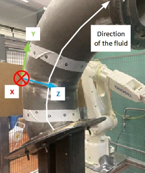
The picture below shows such a pipe with an elbow weld to inspect, with the local coordinate system defined in the application.
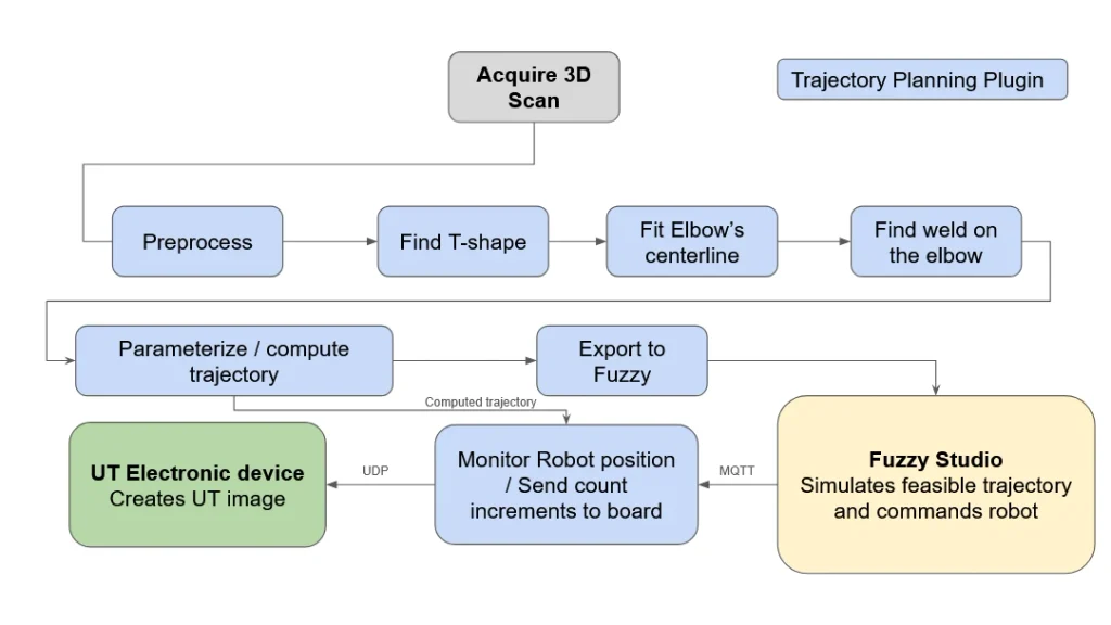
Below, we describe the workflow we implemented to determine meaningful trajectories around the weld of interest, and how they are used in the system to efficiently assist the NDT user.
Preprocessing Step
In the workflow, the user scans the pipe using a 3D sensor on the robotic arm. The resulting scan therefore contains the scanned elbow but also points from the surrounding areas, including the base of the robot itself. To select the relevant part of the 3D data, we added a step of manual segmentation of the elbow.
We also added an option to resample the point cloud and recompute normals with an automatically computed (but tunable) ball size in order to harmonize the inputs received by the following parts of the processing chain.
Other CloudCompare algorithms for cleaning point clouds, such as SOR or Noise filters, can also be used seamlessly to improve data quality before applying the processes described in this workflow.
Referential Determination Step (T-Shape Fit)
To calibrate the position of the point cloud with the robot, the 3D scan must contain a piece of known geometry that is attached to the scanning robot. To that end, a 3D pattern with multiple planes (which we will call T-Shape) has been selected.
This step therefore consists of detecting this pattern in the point cloud based on a known reference point cloud. With this detection, we can define the coordinate system corresponding to this shape and use it as the reference for the poses in the rest of the pipeline.
This step is crucial, as all outputs will then be in this referential and even a small misalignment could lead to an incorrect position of the probe during the measurement.
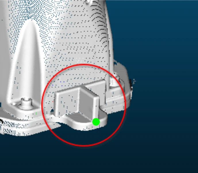
Experimental tests have shown that the repeatability of calibration using this method is much better than the previous workflow. This allowed the users to remove compensation mechanical pieces that were in use to compensate for the inaccuracies in this step, leading to more repeatable and more qualitative measurements.
Shape Detection and Parameterization
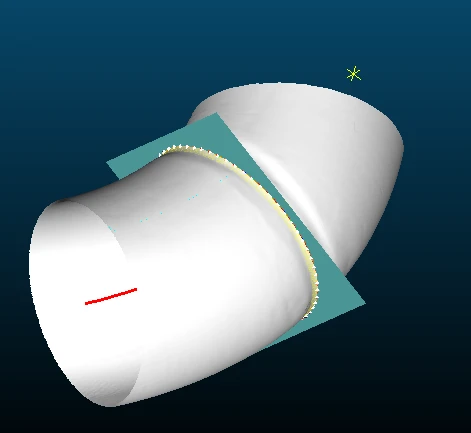
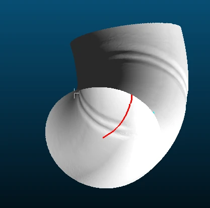
This step detects the shape of interest that we have modelled as a circular shape being translated and oriented around the pipe middle axis, the centerline. For this, we implemented a custom algorithm that iteratively estimates the centerline along the shape.
Note this is a problem similar to finding a centerline in vascular medical imaging as available in ITK.
Weld Detection
Once the overall shape is extracted, the weld appears in the 3D point cloud as a locally slightly larger volume. We implemented a custom method based on local point analysis (leveraging a minimization function to find local maxima in normal orientation relative to the direction of the closest guideline point) to extract the weld.
We also added tools for the user to manually edit it or fit it from a set of 3 or more points, as, in some cases, the shape formed by the weld can vary widely and therefore be very hard to detect automatically.
Trajectory Configuration and Communication with Other Softwares
From there, we compute the trajectories around the weld, given the specifications from Intercontrôle corresponding to the necessary inspections to perform with the UT probe. There are multiple trajectory types that can be configured depending on the area we want to inspect and which type of defect we are looking for (this will not be detailed in this blog).
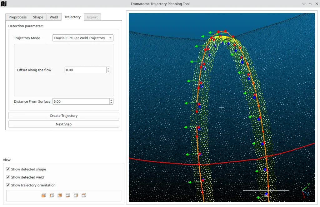
Once this reference trajectory is computed, we can add specific modifications to it, relative to its point density, specific offsets, orientation rules…
It is then exported to Fuzzy Studio, the software that is used to control the robotic arm to validate it in the physical simulation and split it into parts so that it is manageable by the arm.
We implemented a panel in the CloudCompare plugin that allows users to connect to the stream containing the actual robot position (using MQTT protocol, a standard for this type of application) so that we can match it to the trajectory and visualize the live positioning of the arm relative to the 3D model.
In this panel, we can also connect (through UDP protocol) to the edge device responsible for capturing the Ultrasound data to feed it the angular positions of the arm in real time in order to map the UT measurements and create the reconstructed picture that will be used for the analysis, where one of the dimensions corresponds to the angular position of the arm around the elbow.
Conclusion
These custom developments in CloudCompare replaced several software tools that the NDT experts and technicians had to use in order to perform the UT inspections, greatly reducing the workload necessary and the risk of errors when transferring information from one software tool to another.
The solution also improved repeatability of the created trajectories and therefore the traceability of the inspections. This plugin represents significant time savings for the team responsible for the inspections.
We developed this custom solution closely following the needs of the Intercontrole team and helped them define the needed features to match the testing procedure as closely as possible while making it both easy to use and configurable.
We thank them for our long standing cooperation on various topics and for this opportunity to leverage the open source ecosystem even outside of Kitware’s tooling in order to solve practical problems for a safer, more efficient world and to discover the world of NDT.
Going forward, next steps may include:
- Improving the weld detection, using 3D information but also RGB when available.
- Integrating AI models to analyse the NDT signals and locate the potential defect in the weld structures.
- Apply similar processes to other shapes and simplify other inspection procedures.
Contact us if you are interested in building applications involving NDT or inspection using 3D perception or AI model developments!
This project was funded by Framatome Intercontrole